Floating liner

a liner and liner technology, applied in the field of floating liner, can solve the problems of premature popping out of the wire loop, tangles of wires, and tangling of welding wires, and achieve the effect of minimizing entanglement of wires

Active Publication Date: 2006-09-05
LINCOLN GLOBAL INC
View PDF48 Cites 25 Cited by
  • Summary
  • Abstract
  • Description
  • Claims
  • Application Information

AI Technical Summary

Benefits of technology

[0017]The present invention relates to a container for wire arrangement and method for paying out the wire from the container while minimizing entanglement of the wire during the payout and further minimizing the formation of e-scripts in the wire during the paying out of the wire from the container. The invention is particularly directed to the paying out of welding wire from containers for use in automatic or semiautomatic welding; however, the invention has broader application and can be used for the paying out of many different types of wire which are in form of wire stacks or coils and packaged in a container. The invention is also particularly directed to small diameter wire and will be described with particular reference thereto; however, the present invention can be used to payout other types of wire.

Problems solved by technology

There are various causes of tangling of the welding wire as it is being withdrawn from a wire stack or coils of welding wire within the supply container.
For instance, wire tangles can be caused by poor drive roll alignment in the feeder which can introduce a twist in the wire.
The twist in the wire can cause the wire to move back into the drum and subsequently cause premature popping out of wire loop as it is being paid out from the container.
Tangling of the wire can also result from inconsistent loop diameter of the wire in the container and inconsistent fan-out of the loops of wire in the container.
In both of these situations, the wire can prematurely pop up and subsequently form tangles as the wire is being paid out from the container.
Tangles can further be caused by the settling of the wire during transportation, and abuse in handling the drum of wire.
Wire tangles can also be caused when a small amount of wire is left on the wire stack or coils in the drum or container and there is a long unsupported coil of the wire from the wire stack or coils toward the upper cover of the container.
In this instance, the wire can get ahead of itself and allow an extra turn to be released, thus becoming tangled.
Both of these structures are costly, and the rotating mechanism is rigid thus not adaptive as the stack is paid down when the wire is consumed.
The space between the guide and the top of the stack increases as the stack lowers, thus cannot prevent premature pop-outs of the welding wire.
The smaller diameter of the opening in the top of the payout mechanism also makes it difficult for a free convolution of wire to find its way to tangle from the outside by snapping over the top of a retaining ring.
Any e-script or twist in the welding wire can result in downtime on a work piece during a welding process.
Any e-script or twist can cause the welding wire to become jammed in a welding gun or wire feeder and / or cause an interruption in the uniform feeding of the welding wire through a wire feeder and / or welding gun.
As a result, these e-scripts or twists in the welding wire can cause the welding wire to jam in a wire feeder or welding gun, the welding process must temporarily terminated to dislodge the jammed welding wire, thus resulting in interruption of the welding process, which can be especially costly and time consuming for automated welding processes.
One or the primary defects of prior wire containers was the inability to deal with excess and unsupported wire between the top of the hat and the retaining ring.
After the wire left the top of the stack and escaped the constraint imposed by the retaining ring, the wire is essentially loose, unsupported and unstable until the wire reaches the top of the hat and enters the liner above the hat wherein the wire is once again supported.
During the payout of the wire, the welding wire becomes unbalanced and typically has a residual twist.
The premature popping out of the wire in turn can result in the formation of knots in the wire.
A surface of the passageway which creates high friction contact between the welding wire and the surface of the passageway could result in nonuniform and / or impeded movement of the welding wire through the floating liner thereby potentially impairing the feed speed and / or force fluctuation causing wire excursion and gun chatter.

Method used


Image

  • Floating liner
  • Floating liner
  • Floating liner

Examples


Embodiment Construction

[0058]Referring now to the preferred embodiment of the drawings, wherein the showings are for the purpose of illustrating a preferred embodiment of the invention only and not for the purpose of limiting the invention,

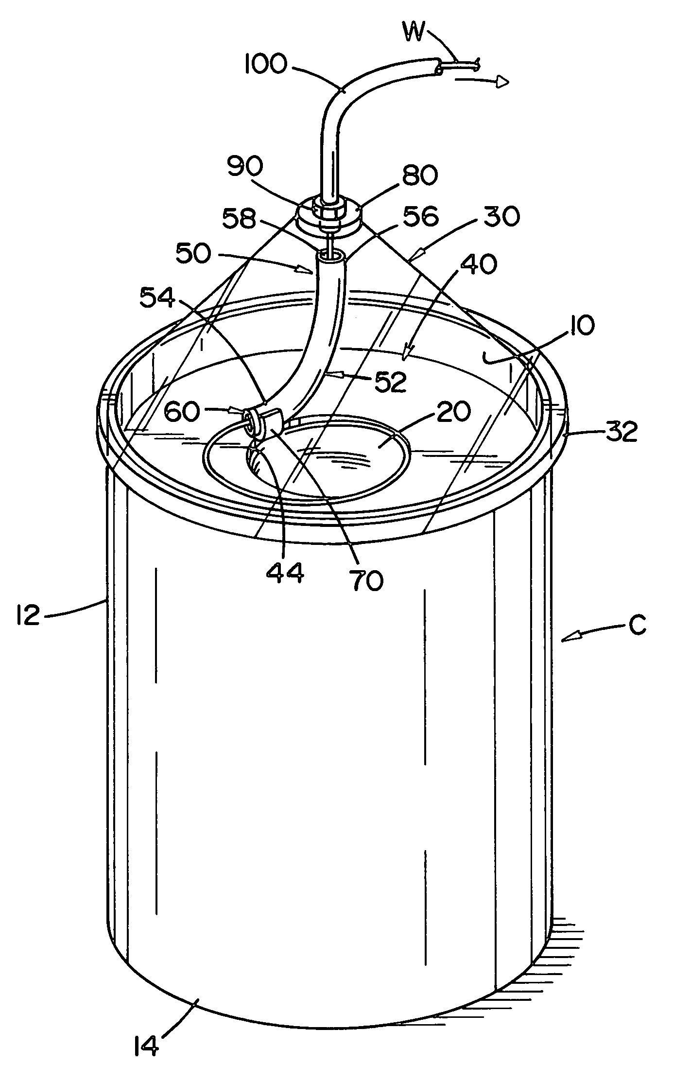
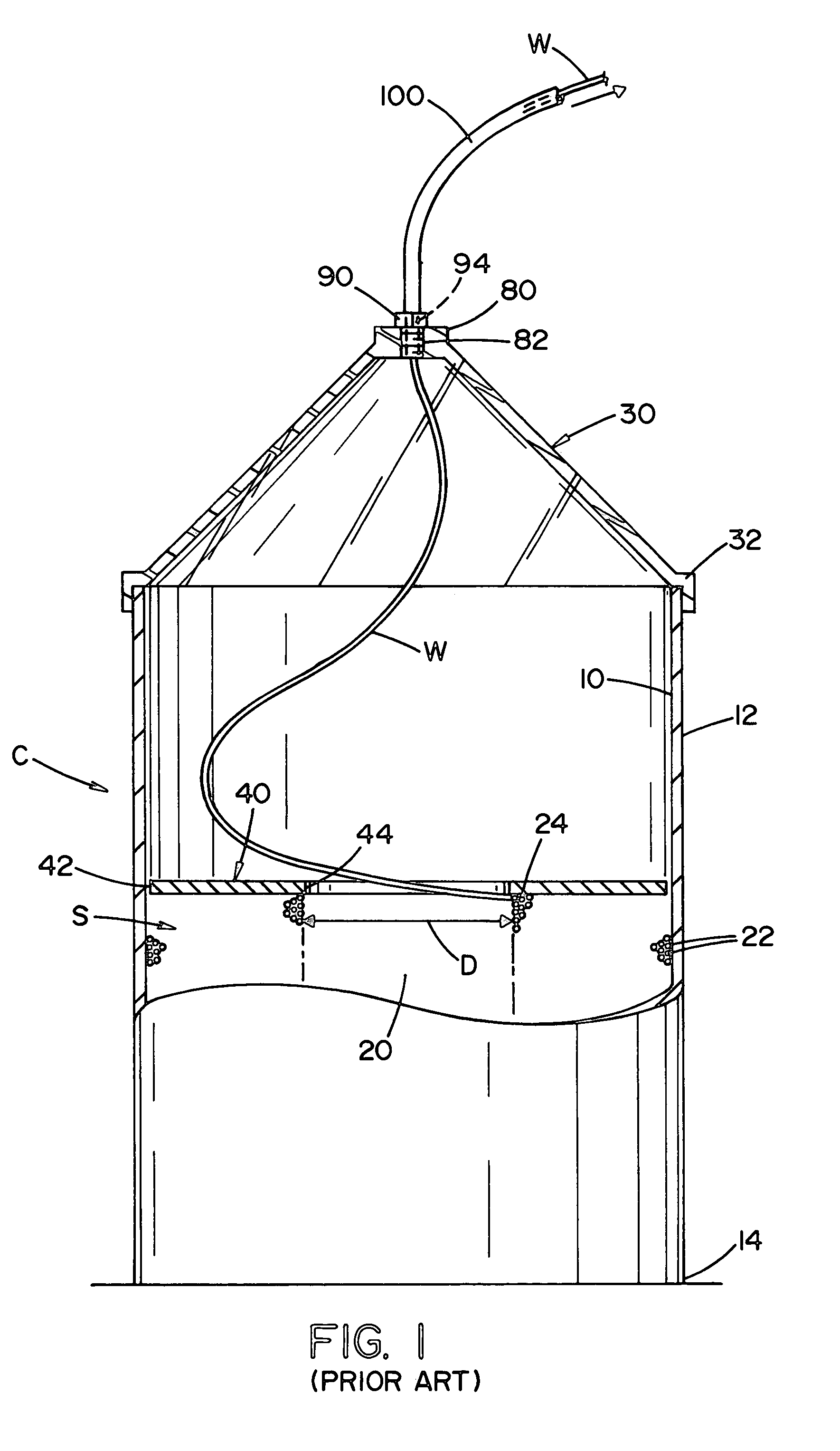
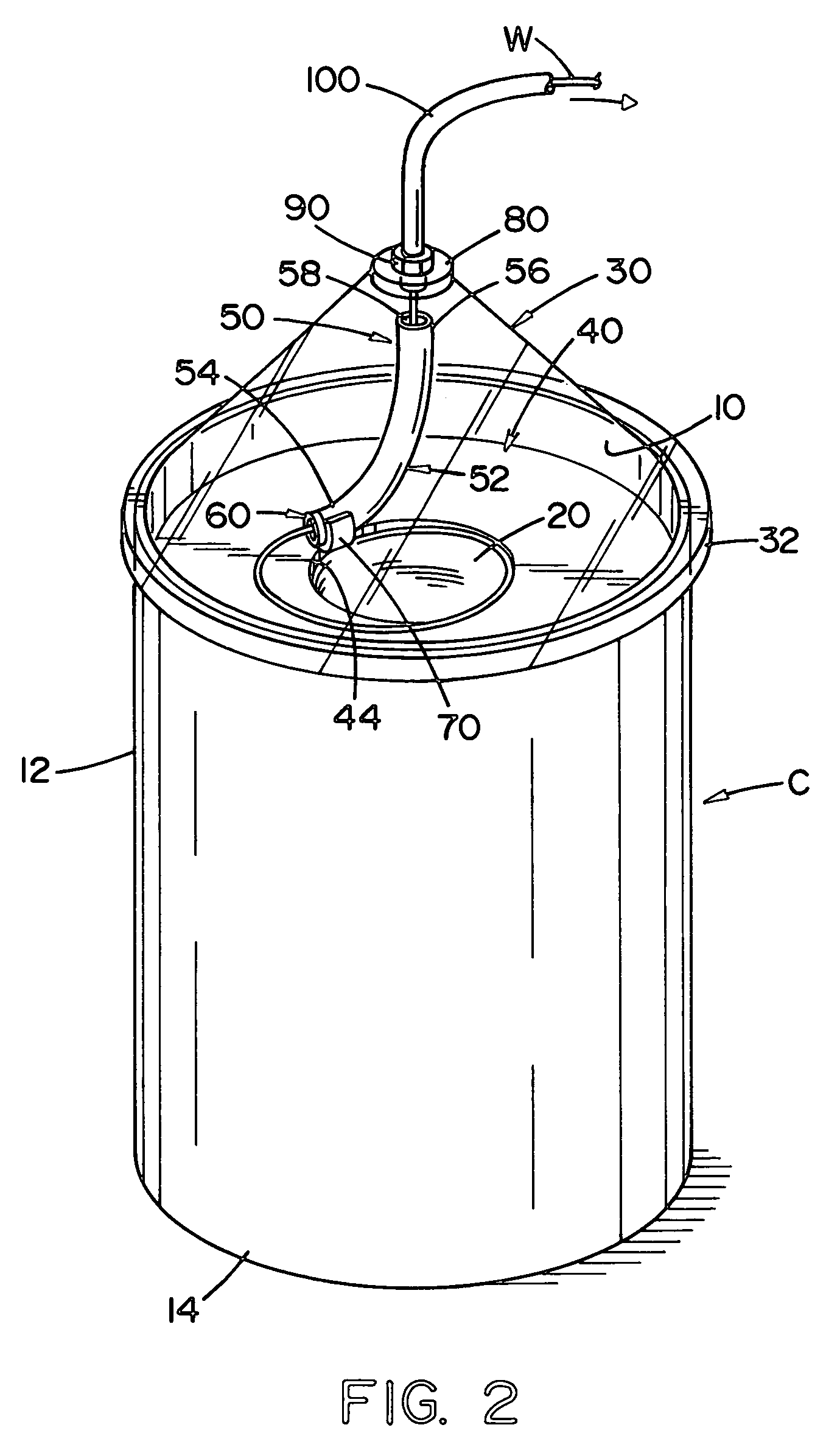
[0059]FIG. 1 illustrates a prior art container C used in dispensing a no-twist welding wire for automatic and / or semiautomatic welding. The container includes a standard drum, hereinafter referred to as the container, which container may be formed of cardboard or other materials and has an interior wall 10, and outer wall 12, and a base 14. Within the container is stored a large volume of welding wire in the form of a wire stack or coils S having an internal cavity 20 with an internal diameter D. The wire stack or coils wire is formed from several convolutions or layers 22 of no-twist wire. The upper portion of the wire stack or coils includes generally flat top surface layers 22 of welding wire. As the welding wire is withdrawn from wire stack or coils S, it first come...


PUM

PropertyMeasurementUnit
weight distributionaaaaaaaaaa
lengthaaaaaaaaaa
inner diameteraaaaaaaaaa

Abstract

A floating liner for a container of welding wire which floating liner includes a tube having two ends and a passageway extending between the two ends. The floating liner is unsupported between the top of the container and the retaining ring. The floating liner is designed to provide structural support to the wire and added stiffness or rigidity to the wire to inhibit buckling of the wire, knot formation in the wire that can form between the retaining ring and the top of the container. The floating liner has a weight profile that causes one end of the tube to at least partially float above the top surface of a layer of welding wire or retaining ring in the container as the welding wire is paid out of the container.

Description

[0001]The invention relates to the art of feeding welding wire from a bulk storage container, and particularly to an improved container for wire, and more particularly liner for a welding wire container that enhances the payout of the welding wire from the container for mass production welding.INCORPORATION BY REFERENCE[0002]Incorporated by reference is Cooper U.S. Pat. No. 5,277,314 and Dragoo U.S. Pat. No. 5,758,834 which disclose bulk storage containers that can be used in the present invention. These patents also disclose and discuss the background in the art to which the present invention is specifically directed. By incorporating these patents by reference, the problems to which the present invention is directed and the background of the field of art need not be repeated in detail.BACKGROUND OF INVENTION[0003]The present invention is particularly applicable for use in a container of welding wire stored as a large wire stack or coils or wire containing convolutions formed into ...

Claims


Application Information

Patent Timeline
Patent Type & Authority Patents(United States)
IPC IPC(8): B65H23/00B21C47/20B23K9/133B65H49/08B65H57/12B65H57/18
CPCB21C47/20B23K9/133B65H57/18B65H49/08B65H57/12B23K9/1333B65H57/00
Inventor HSU, CHRISTOPHERBARTON, DAVID J.CARROSCIA, MICHAEL A.
Owner LINCOLN GLOBAL INC
Why Eureka
Try Eureka