Ferrule with relief to reduce galling

Inactive Publication Date: 2006-09-05
SWAGELOK CO
View PDF120 Cites 990 Cited by
  • Summary
  • Abstract
  • Description
  • Claims
  • Application Information

AI Technical Summary

Benefits of technology

[0011]In accordance with one embodiment of the invention, a tube fitting includes a fitting body having a cylindrical bore for receiving a tube end and including a tapered mouth at one end of the bore; a drive member having a threaded engagement with the body and having a ferrule drive surface; a first ferrule having a tapered first end that extends into the tapered mouth of the fitting body and having a second end with a tapered recess that axially extends toward the first end; and a s

Problems solved by technology

The thickness of the nose portion cannot be reduced to an extent that the rear ferrule deforms too much and only the rear ferrule adequately grips the outer wall of the tubing.
On the other hand, the thickness of the nose of the rear ferrule cannot be

Method used


Image

  • Ferrule with relief to reduce galling
  • Ferrule with relief to reduce galling
  • Ferrule with relief to reduce galling

Examples


Embodiment Construction

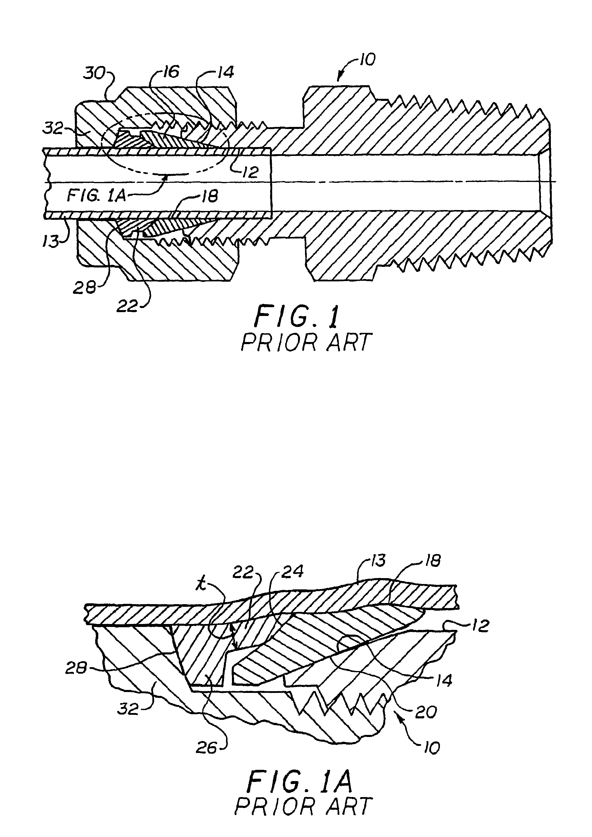
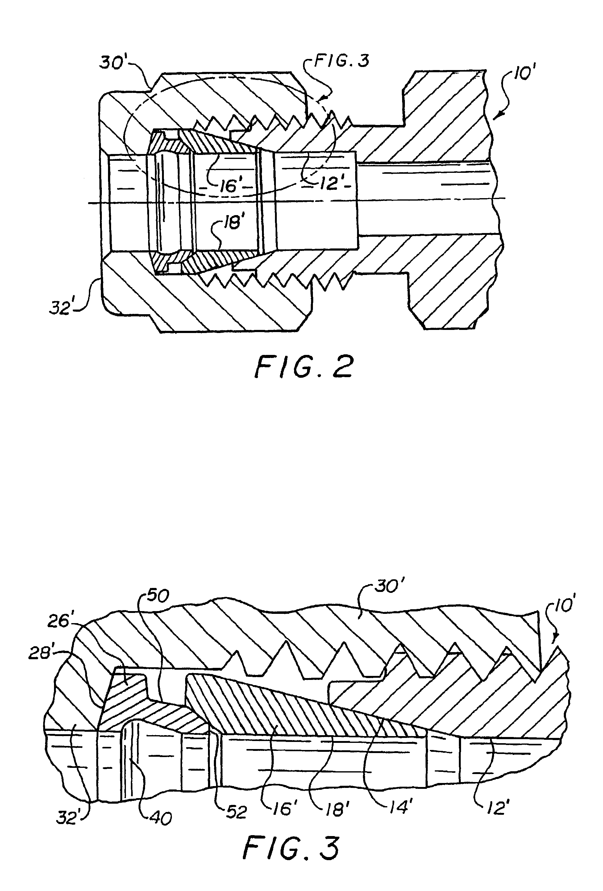
[0044]Referring now to the drawings wherein the showings are for the purposes of illustrating preferred embodiments of the invention only and not for purposes of limiting same, FIGS. 2–4 illustrate the overall arrangement of a fitting incorporating the invention. It should be noted that in many of the illustrations herein of the ferrule profiles, the ferrules are shown in partial cross-section for clarity and ease of understanding, particularly for views of the ferrule geometry. and profile wherein it is only necessary to illustrate a portion of the entire ferrule in sectional view. The FIGS. 2–4 embodiment has the major components identified with the same reference numerals used with respect to the description of the prior art device of FIGS. 1 and 1A. A description of a FIG. 1 element is to be taken as equally applicable to the FIGS. 2–4 elements that are correspondingly numbered unless otherwise noted. In particular, in the FIGS. 2–4 embodiment, the rear ferrule 22′ has been modi...


PUM


Abstract

High localized loading, galling, and high torque forces have been generally eliminated or greatly reduced in a two ferrule tube fitting assembly through suitable modification of the rear ferrule so as to redirect the reaction forces acting between the front ferrule and the drive nut. The rear ferrule has a cylindrical interior wall that closely surrounds the tube end and is provided on the interior cylindrical wall with a circumferentially continuous radial recess that is located between the nose and rear wall of the rear ferrule. The rear ferrule also has a radially external wall that is substantially conical and additionally shaped to extend radially outward toward the enlarged diameter portion or flange of the rear ferrule. The rear ferrule further includes a contoured face on the rear driven surface of the ferrule that engages the drive surface of the drive nut.

Description

RELATED APPLICATIONS[0001]This application is a continuation of allowed U.S. patent application Ser. No. 09 / 469,549 filed on Dec. 12, 1999, now U.S. Pat. No. 6,629,708 for FERRULE WITH RELIEF TO REDUCE GALLING, which is a continuation-in-part of U.S. patent application Ser. No. 09 / 054,186 filed on Apr. 2, 1998, now U.S. Pat. No. 6,131,963, which is a continuation-in-part of U.S. patent application Ser. No. 08 / 834,255 filed on Apr. 15, 1997, now U.S. Pat. No. 5,882,050, the entire disclosures of which are fully incorporated herein by reference.BACKGROUND OF THE INVENTION[0002]The subject invention is directed to the art of ferrule type tube fittings. More particularly, the invention concerns a two ferrule fitting wherein the rear ferrule is designed to reduce the torque required to rotate the associated nut and to also reduce galling between the rear ferrule and the interior surface of the drive nut. The invention may also be applied in a single ferrule fitting.[0003]A commercially a...

Claims


Application Information

Patent Timeline
IPC IPC(8): F16L19/10F16L19/06
CPCF16L19/103F16L19/10
Inventor WILLIAMS, PETER C.KUHNS, HOWARD C. B.
Owner SWAGELOK CO
Why Eureka
Try Eureka