Water gate locker

a technology for water gate lockers and lockers, applied in the field of water gate lockers, can solve the problems of not being designed well, needing urgent improvement, and above-mentioned conventional water gate lockers still have drawbacks, and achieve the effect of simple structure and easy manufactur

Inactive Publication Date: 2006-09-05
TYRONE MARINE HARDWARE
View PDF4 Cites 51 Cited by
  • Summary
  • Abstract
  • Description
  • Claims
  • Application Information

AI Technical Summary

Benefits of technology

[0008]The object of the present invention is to provide a water gate locker, in which the position-ring combined at the lower end of the press-bolt is used to unlock / lock the fastener-portion of the bracket, that can achieve the effect of which allows the locker body to be positioned easily and come off unlikely.
[0009]The another object of the present invention is to provide a water gate locker having many advantages, such as a simple structure, easy manufacture, etc,.
[0011]First, the turning-axle of the locker body is fitted in the axle-hole of the bracket, and then the turning-axle of the locker body with a spacer is penetrated in the axle-hole of the protrudent-cylinder of the bracket. After the turning-axle is inserted into the axle-hole of the protrudent-cylinder, a spacer-ring is fitted in the turning-axle and fixed by using a nut to be screwed on the thread at the front end of the turning-axle, thus the bracket and the locker body can be united firmly, and then a spring is placed in the hole of the locker body and the press-bolt is inserted into the spring, at this time, the column at the lower end of the press-bolt will be inserted into the hole of the spacer, and then the fastener-portion of the bracket is inserted into the protrudent-cylinder, and then a position-ring is combined with the column at the lower end of the press-bolt, thus the press-bolt cannot depart from the hole of the locker body, and finally, a seal-plate is provided to combine with the protrudent-cylinder of the bracket. Thus, after the all above-mentioned components are assembled, the water gate locker of the present invention is formed.

Problems solved by technology

Thus it can be seen, the above-mentioned conventional water gate locker still has drawbacks, not designed well actually, and need improved urgently.

Method used


Image

  • Water gate locker
  • Water gate locker
  • Water gate locker

Examples


Embodiment Construction

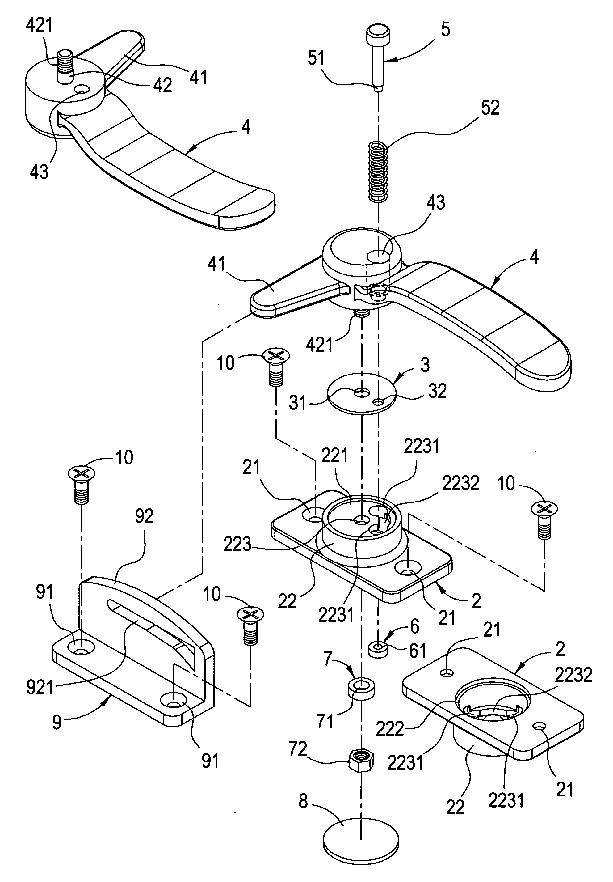
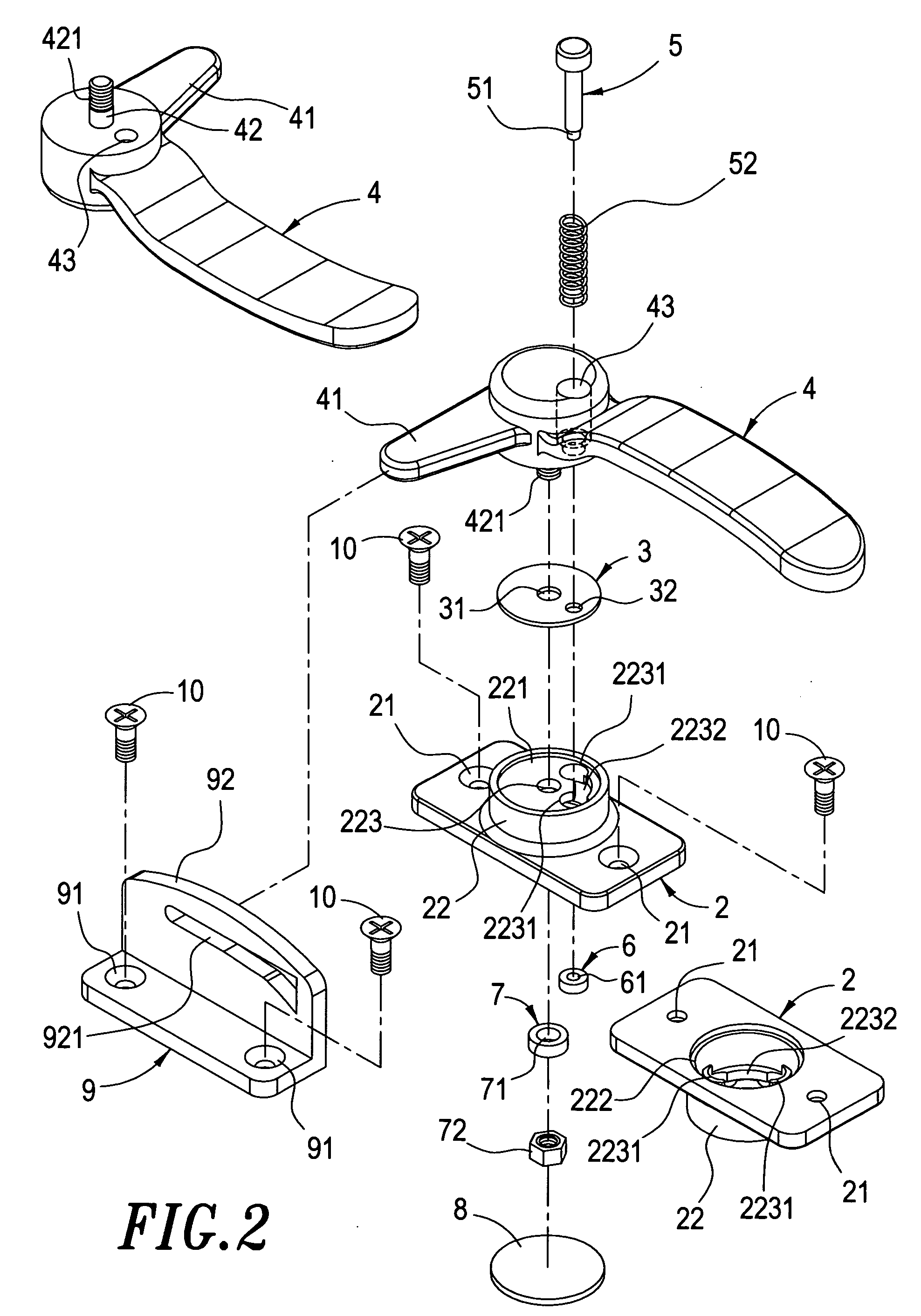
[0017]As shown in FIGS. 2 and 3, a water gate locker according to the present invention mainly comprising:

[0018]a bracket 2, in which a screw-hole 21 is provided at each side of the bracket 2, and a protrudent-cylinder 22 is protruded upward from the middle of bracket 2, and the inside of the protrudent-cylinder 22 is hollow, and a pit-portion 221 is concaved on the upper side of the protrudent-cylinder 22, a fillister 222 is concaved on the lower side of the protrudent-cylinder 22, and an axle-hole 223 is penetrated in the middle of the protrudent-cylinder 22, and two fastener-portions 2231 are penetrated at suitable locations beside the axle-hole 223, and a runner 2232 in an arc form with smaller diameter is penetrated between the two fastener-portions 2231 so that the two fastener-portions 2231 and the runner 2232 are channelized; thus the screw-holes 21 can be used to position the bracket with screws 10;

[0019]a spacer 3, in which an axle-hole 31 is provided at the middle of the ...


PUM


Abstract

A water gate locker comprises a locker body, a bracket, a fastener-seat, a press-bolt, a position-ring, a nut. A position-slice is extended from one side of the locker body and a turning-axle is extended downward from the bottom of the locker body, and a thread is provided at the front end of the turning-axle, and a hole, with the upper portion larger than the lower, is provided on the locker body, and is penetrated through by a press-bolt, a screw-hole is provided at each side of the bracket, and a protrudent-cylinder is protruded upward from the middle of bracket, and an axle-hole is penetrated through the protrudent-cylinder, and two fastener-portions are penetrated beside the axle-hole, and a runner in an arc form with smaller diameter is penetrated between the two fastener-portions, a screw-hole is provided at each side of the fastener-seat, and a position-plate is extended upward from a side of the fastener-seat, and a position-runner is provided on a suitable portion of the position-plate, the turning-axle of the locker body is fitted in the axle-hole of the protrudent-cylinder of the bracket, and the locker body is integrated with the bracket via a nut, and the bottom end of the press-bolt is protruded from the runner of the protrudent-cylinder, and then a position-ring is combined with the bottom end of the press-bolt. Accordingly, the water gate locker according to the present invention is formed.

Description

BACKGROUND OF THE INVENTION[0001]1. Field of the Invention[0002]The present invention relates to a water gate locker, particularly to a water gate locker, in which a positioning device is installed in the locker body, which facilitates achieving the position of the water gate by using said positioning device.[0003]2. Description of the Prior Art[0004]FIG. 1 shows the structural schematic diagram of a conventional water gate locker, which mainly comprises a locker 11, a position-seat 12, and a fastener-seat 13, wherein the locker 11 has an extended position-slice 111 at one side thereof, combined with a position-seat 12, and connected with the position-seat 12 each other by using a position-bolt 112; a position-runner 131 is provided on the fastener-seat 13; when the user want to close the water gate, the user only needs to turn the locker 11 90° to allow the position-slice 111 of the locker 11 to be locked in the position-runner 131 on the fastener-seat 13, and thus achieving the po...

Claims


Application Information

Patent Timeline
Patent Type & Authority Patents(United States)
IPC IPC(8): E05C3/12E05C3/14
CPCE05B13/002E05C3/043Y10S292/37Y10T292/1039Y10T292/1041Y10T292/1089Y10T292/225Y10T292/57
Inventor JIEN, LEE-WEN
Owner TYRONE MARINE HARDWARE
Why Eureka
Try Eureka