Turbomachine blade, in particular a fan blade, and its method of manufacture

a technology of turbine blades and turbine blades, which is applied in the direction of machines/engines, weaving, liquid fuel engines, etc., can solve the problems of requiring a plurality of parts, difficult techniques, long and expensive,

Active Publication Date: 2006-09-05
SN DETUDE & DE CONSTR DE MOTEURS DAVIATION S N E C M A
View PDF7 Cites 106 Cited by
  • Summary
  • Abstract
  • Description
  • Claims
  • Application Information

AI Technical Summary

Benefits of technology

[0006]An object of the present invention is to provide a preform of yarns or fibers woven in three dimensions and sufficing on its own, possibly after being cut to shape, and after injection, to constitute the final part forming the turbomachine blade, without requiring the use of inserts or any other fitted element.
[0013]In an highly advantageous disposition, the shrinkage angle of the warp yarns lies in the range 2° to 10°, whether in the first portion (blade body) or in the second portion (blade root). Thus, by means of this small value, strong cohesion is conserved between the warp yarns and the weft yarns woven between them in a three-dimensional configuration, thereby obtaining a blade having good impact strength, since the energy of the impact is easily absorbed, which means that any damage remains very localized.
[0014]In another advantageous disposition, said first portion and said second portion present different warp / weft volume ratios. This technique of modifying fiber density also presents the additional advantage of enabling the shrinkage angle (the angle between a warp yarn or a weft yarn relative to a horizontal plane) between the first weave (first portion) and the second weave (second portion) to be modified, which has a direct influence on the mechanical properties of the two corresponding portions, in particular on their moduluses of elasticity and on their impact strengths, and also on the relative thicknesses of the first and second portions.
[0016]Also, in preferred and advantageous manner, the count of the warp yarns varies between the edge and the remainder of the blade, the warp yarns at the edge being finer, thus making it possible also to modify the mechanical properties of the blade between its surface and its central portion, both in the root (second portion) and in the body (second portion) of the blade.

Problems solved by technology

That technique is very difficult and requires plie-stacking operations to be performed manually, which is lengthy and expensive.
Those techniques (U.S. Pat. No. 5,672,417 and U.S. Pat. No. 5,013,216) nevertheless present the drawback of requiring a plurality of parts to assembled together and of creating, in such assemblies, zones constituting privileged sites for weakness, e.g. by delamination, which is very harmful in terms of mechanical strength, in particular for ability to withstand impacts.

Method used


Image

  • Turbomachine blade, in particular a fan blade, and its method of manufacture
  • Turbomachine blade, in particular a fan blade, and its method of manufacture
  • Turbomachine blade, in particular a fan blade, and its method of manufacture

Examples


Embodiment Construction

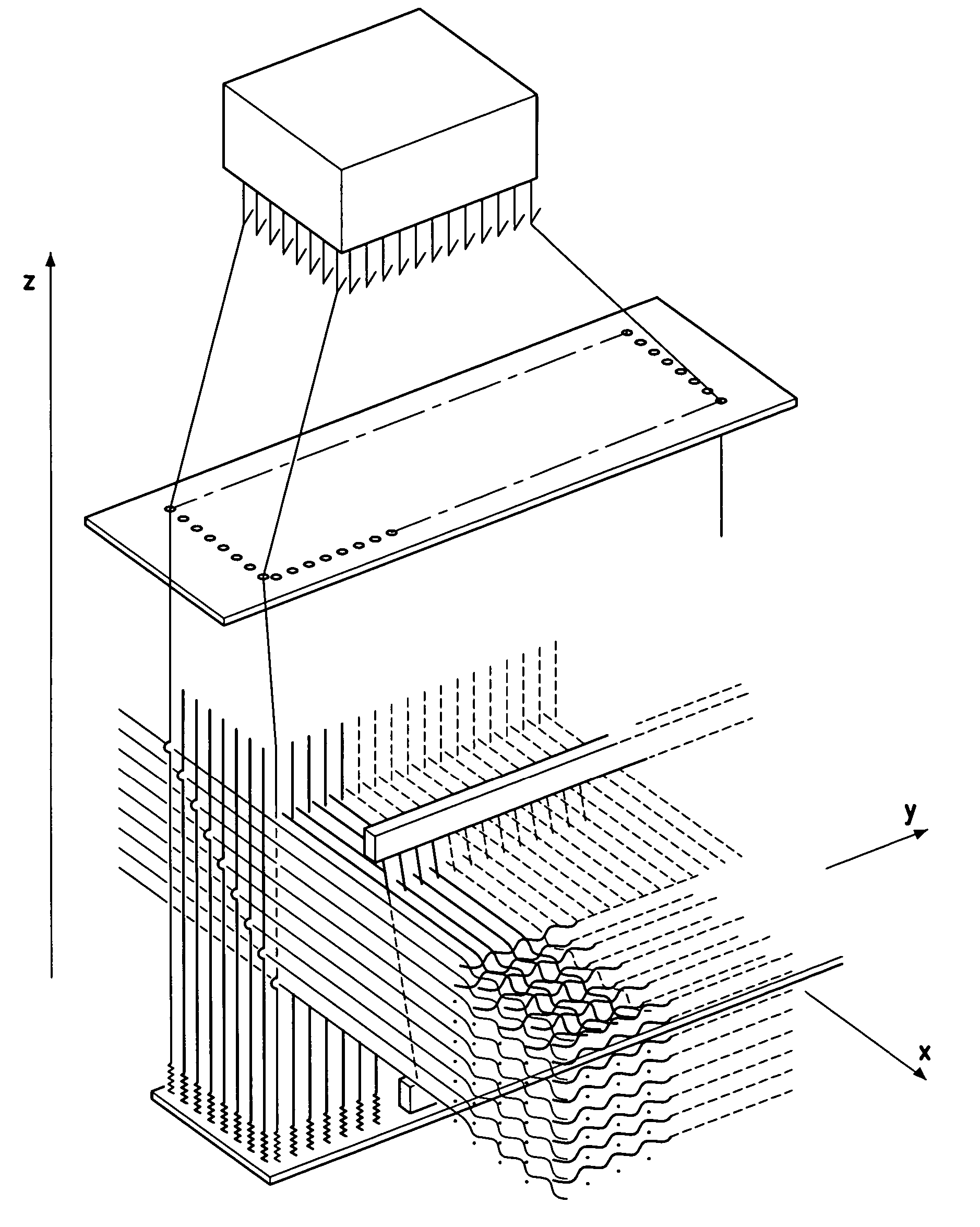
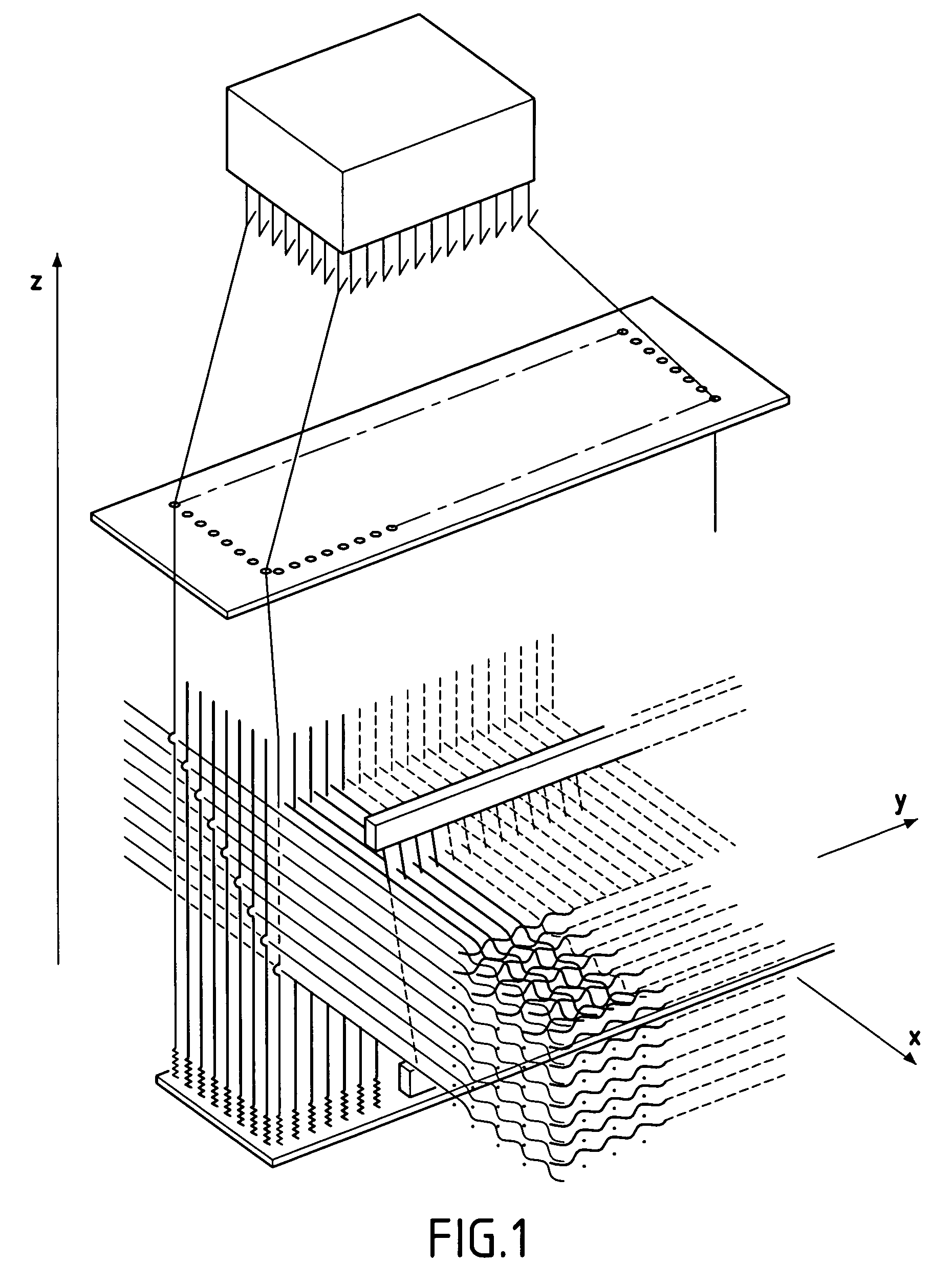
[0059]In the description below, the longitudinal direction, the transverse direction, and the vertical direction correspond respectively to the directions of arrows x, y, and z in the figures.

[0060]FIG. 1 is a diagram showing a Jacquard-type loom having the warp yarns mounted thereon which are oriented in the longitudinal direction (arrow x) and which extend in a plurality of layers superposed in the vertical direction (arrow z), together with the weft yarns which are oriented in the transverse direction (arrow y).

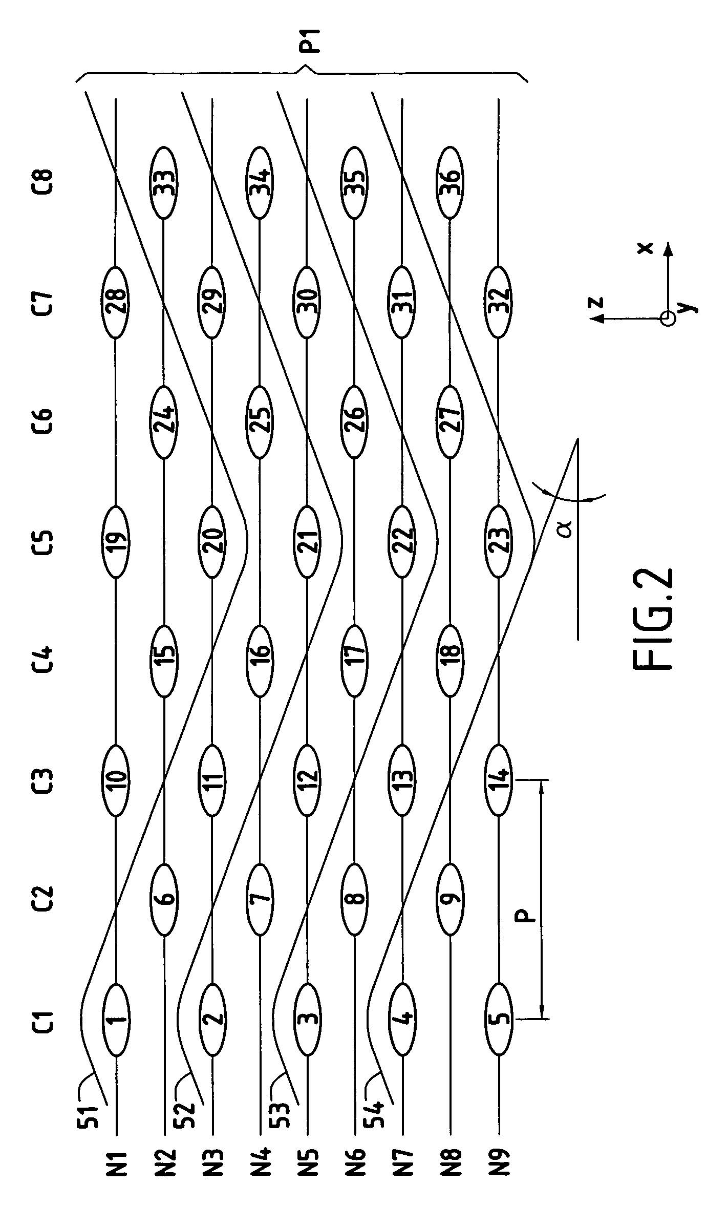
[0061]FIGS. 2 to 9 show the base pattern of the first weave for a preform in accordance with the present invention. This first weave comprises thirty-six weft yarns 1 to 36 (i.e. they are shown in section) disposed in a staggered configuration on nine superposed levels N1 to N9, and distributed in eight columns C1 to C8, comprising:[0062]a first column C1 of five superposed weft yarns 1 to 5 situated respectively at levels N1, N3, N5, N7, and N9;[0063]a second column C2 of...


PUM

PropertyMeasurementUnit
shrinkage angleaaaaaaaaaa
step sizeaaaaaaaaaa
step sizeaaaaaaaaaa

Abstract

The composite turbomachine blade of the present invention comprises a preform made of yarns or fibers woven in three dimensions and a binder maintaining the relative disposition between the yarns of the preform. Said preform is made up of warp yarns and of weft yarns, the direction of the warp yarns forming the longitudinal direction of the preform. In characteristic manner, said preform comprises at least a first portion made using a first weave forming the airfoil of the blade, and a second portion made using a second weave forming the root of the blade, and the first and second portions are united by a transition zone in which the first weave is progressively modified to end up with the second weave, thereby obtaining a reduction at least in the thickness of the blade between the second portion and the first portion. The invention is applicable to making a fan blade for a turbojet.

Description

[0001]The invention relates to a composite turbomachine blade comprising a preform of yarns or fibers woven in three dimensions and a binder maintaining the relative disposition between the yarns of the preform, said preform being made up of warp yarns and of weft yarns, the direction of the warp yarns forming the longitudinal direction of the preform.[0002]In more particular manner, the present invention relates to a fan blade for a turbojet.[0003]The present invention also relates to a method of manufacturing such blades.BACKGROUND OF THE INVENTION[0004]In usual manner, fan blades made of composite material, in particular using carbon fibers, are made from a stack of pre-impregnated unidirectional plies which are placed in a mold with the successive plies being oriented differently, prior to compacting and polymerizing in an autoclave. That technique is very difficult and requires plie-stacking operations to be performed manually, which is lengthy and expensive.[0005]Proposals hav...

Claims


Application Information

Patent Timeline
Patent Type & Authority Patents(United States)
IPC IPC(8): F04D29/38B29C70/48D03D15/12D03D25/00F01D5/28F02C7/00F04D29/02F04D29/32
CPCB29C70/48D03D25/005F01D5/282F04D29/324F04D29/023B29B11/16B29C70/24Y10T29/49337Y02T50/672F05D2300/6012Y10T29/49336F05D2300/603F05D2300/614Y10T442/3195Y02T50/60
Inventor DAMBRINE, BRUNOMOLINARI, OLIVIERCOUPE, DOMINIQUE
Owner SN DETUDE & DE CONSTR DE MOTEURS DAVIATION S N E C M A
Why Eureka
Try Eureka