Retractable scalpel

a scalpel and retraction technology, applied in the field of scalpels, can solve problems such as accidental retraction of blades, and achieve the effect of eradicating accidental stabs

Active Publication Date: 2006-09-05
GEORGE SAMUEL +1
View PDF6 Cites 68 Cited by
  • Summary
  • Abstract
  • Description
  • Claims
  • Application Information

AI Technical Summary

Benefits of technology

[0014]The sliding piece is connected at a rearward point to one end of a spring. The other spring end is connected with a rearward part of the interior of the cover housing. When the scalpel blade is in an extended position, each releasable latching element is accessible for depression by finger pressure to cause retraction of the extended blade. However, the releasable latching elements are located on opposite edges (top and bottom edges) of a cover housing and about halfway along its length. The releasable latching elements must be depressed at the same time for the extended scalpel blade to be retracted into the cover housing. Because the releasable latching elements are located in a low profile elevation with respect to the outside surface of the cover housing, the releasable latching elements cannot be inadvertently be depressed simultaneously to result in accidental blade retraction.
[0015]In addition, locating the releasable latching elements on top and bottom edges and about halfway down a length of the cover housing virtually eliminates accidental release. In use, the cover housing is essentially the scalpel handle and a user will firmly compress a forward part of that cover housing with their thumb and opposing fingers. A user may accidentally depress a bottom edge of the cover housing in vigorous downward strokes of the scalpel. However, simple ergonomics of the human palm eliminates the possibility of the releasable latching element on the top edge from being depressed at the same time. In such vigorous downward strokes of a scalpel, the thumb presses sideways against a left and forward side of the cover housing, the index finger presses on the opposite right side of the cover housing, the other fingers may curl around the botto...

Problems solved by technology

Because the releasable latching elements are located in a low profile elevation with respect to the outside surface of the cover ...

Method used


Image

  • Retractable scalpel
  • Retractable scalpel
  • Retractable scalpel

Examples


Embodiment Construction

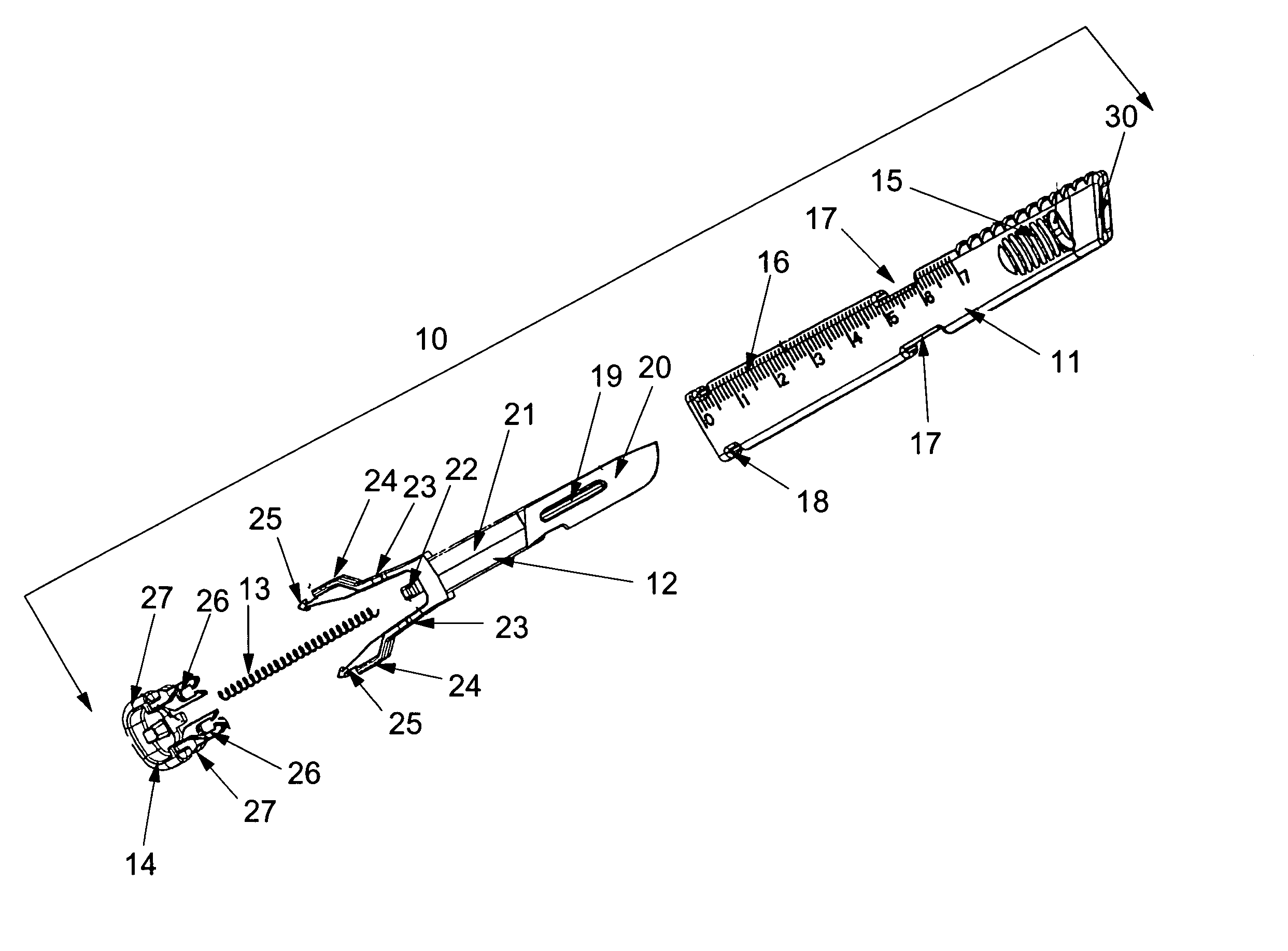
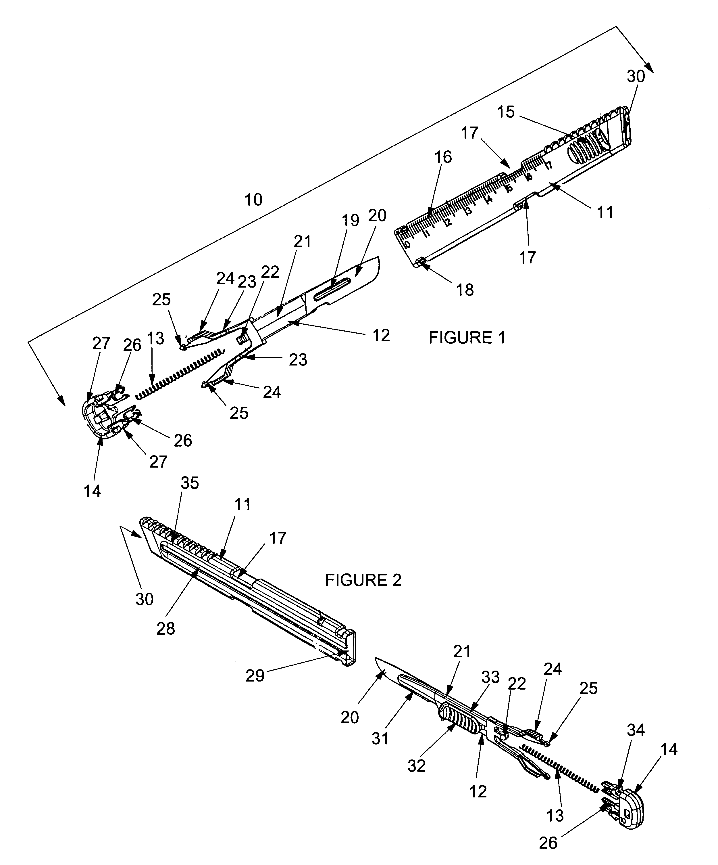
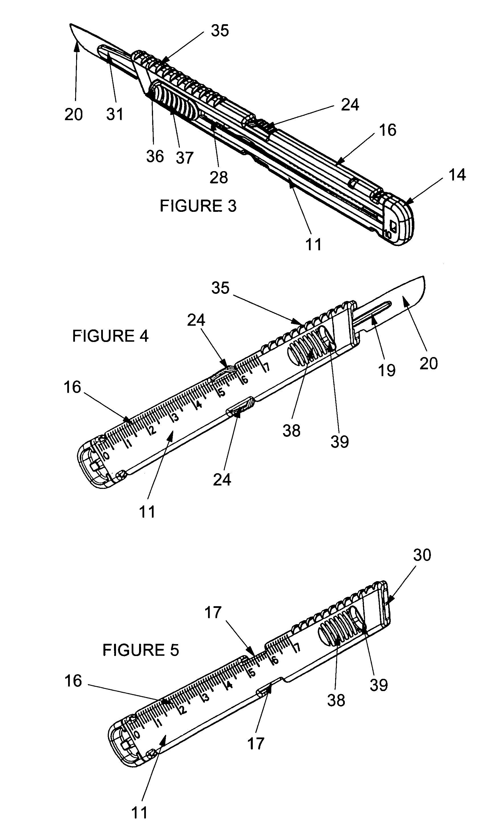
[0031]The invention is now discussed with reference to the figures. FIGS. 1 through 8 show several aspects of the invention retractable scalpel. The scalpel 10 comprises a cover housing (with housing 11 and end cap 14), a scalpel blade 20, a sliding piece 12, and a spring 13. The assembled scalpel 10 is shown in FIGS. 3, 4, 6, 7, and 8.

[0032]The cover housing is generally formed like a scalpel handle. It may not be thicker than about three eighths of an inch and is preferably about one fourth of a inch or less. This limitation has in the past condemned retractable scalpels to be either too thick (sufficient structural support) or too thin (the handle part is too flexible and bends too much during critical steps in a procedure). The present invention has achieved exceptional resistance to bending while maintaining a desired thickness of the cover housing. Housing 11 comprises a generally rectangular shape with a bore extending from opening 30 to opening 29, where slot 28 extends from...


PUM


Abstract

The present invention is a retractable scalpel device with two releasable latching elements. When the scalpel blade is in an extended position, each releasable latching element is accessible for depression by finger pressure to cause retraction of the extended blade. However, the releasable latching elements are located on opposite edges (top and bottom edges) of a cover housing and about halfway along its length. The releasable latching elements must be depressed at the same time for the extended scalpel blade to be retracted into the cover housing.

Description

[0001]This application is a continuation in part of Ser. No. 60 / 425,866 filed Nov. 12, 2002 now abandoned.BACKGROUND OF THE INVENTION[0002]The present invention relates to disposable scalpels and, in particular, to retractable-blade types thereof.[0003]Medical personnel, especially highly skilled surgeons, are at risk every day from accidental stabbing. Scalpels must be passed from one person to another and back again in surgical procedures. In addition, a surgeon may retain a scalpel in his grasp while trying to use another instrument such as a hemostat or retractor or to adjust an overhead lamp, making it highly likely that an accidental incision or laceration will cause undue harm to a patient or other medical personnel whose hands are nearby.[0004]Injuries arising from the above accidents are known as “sharps” injuries. Medical personnel are always at risk of contracting potentially fatal bacterial and / or, viral infections, including HIV and Hepatitis B and C. It is desirable to...

Claims


Application Information

Patent Timeline
IPC IPC(8): A61B17/32
CPCA61B17/3211A61B2017/32113
Inventor GEORGE, SAMUELHOFTMAN, MIKE
Owner GEORGE SAMUEL
Why Eureka
Try Eureka