
Demand-based memory system for graphics applications

Inactive Publication Date: 2006-09-05
NVIDIA CORP
View PDF14 Cites 95 Cited by
  • Summary
  • Abstract
  • Description
  • Claims
  • Application Information

AI Technical Summary

Benefits of technology

[0006]The present invention provides a memory system and methods of operating the same that drastically increase the efficiency in memory use and allocation in graphics systems. Broadly, in a graphics system using a tiled architecture, instead of pre-allocating a fixed amount of memory for each tile, the present invention dynamically allocates varying amounts of memory per tile depending on the demand. In one embodiment all or a portion of the available memory is divided into smaller “pages” that are preferably equal in size. Memory allocation is done by page based on the amount of memory required for a given tile. The smaller the size of the page the higher the granular resolution, and therefore the more efficient memory allocation becomes. In one embodiment, the size of the page is made configurable. This page-based memory system removes the limitation on the memory size for a single tile by simply allocating more pages when necessary. Therefore, a tile wherein a large amount of geometry may lie would not cause an exception. In one embodiment, when all geometry data stored in a page of memory has been rendered, the page is freed and made available for reallocation. This effectively reduces the overall amount of memory used for binning, eliminating the need for double-buffering for a system that pipelines the binning and the rendering process.

Problems solved by technology

Limited memory bandwidth has been a major obstacle in improving the performance of traditional 3-D graphics pipelines.
While this type of tile-based architecture improves memory bandwidth, it also increases the demand for larger memory.
In this type of memory system inefficiencies arise when, for example, the amount of geometry data for a given tile is larger than the pre-allocated amount of memory.
This results in the inability of the graphics hardware to process all the data and render the tile.
Conversely, a particular tile with a small amount of geometry data may require less memory than that provided by the pre-allocated memory resulting in portions of the pre-allocated memory to go unused.

Method used


Image

  • Demand-based memory system for graphics applications
  • Demand-based memory system for graphics applications
  • Demand-based memory system for graphics applications

Examples


Embodiment Construction

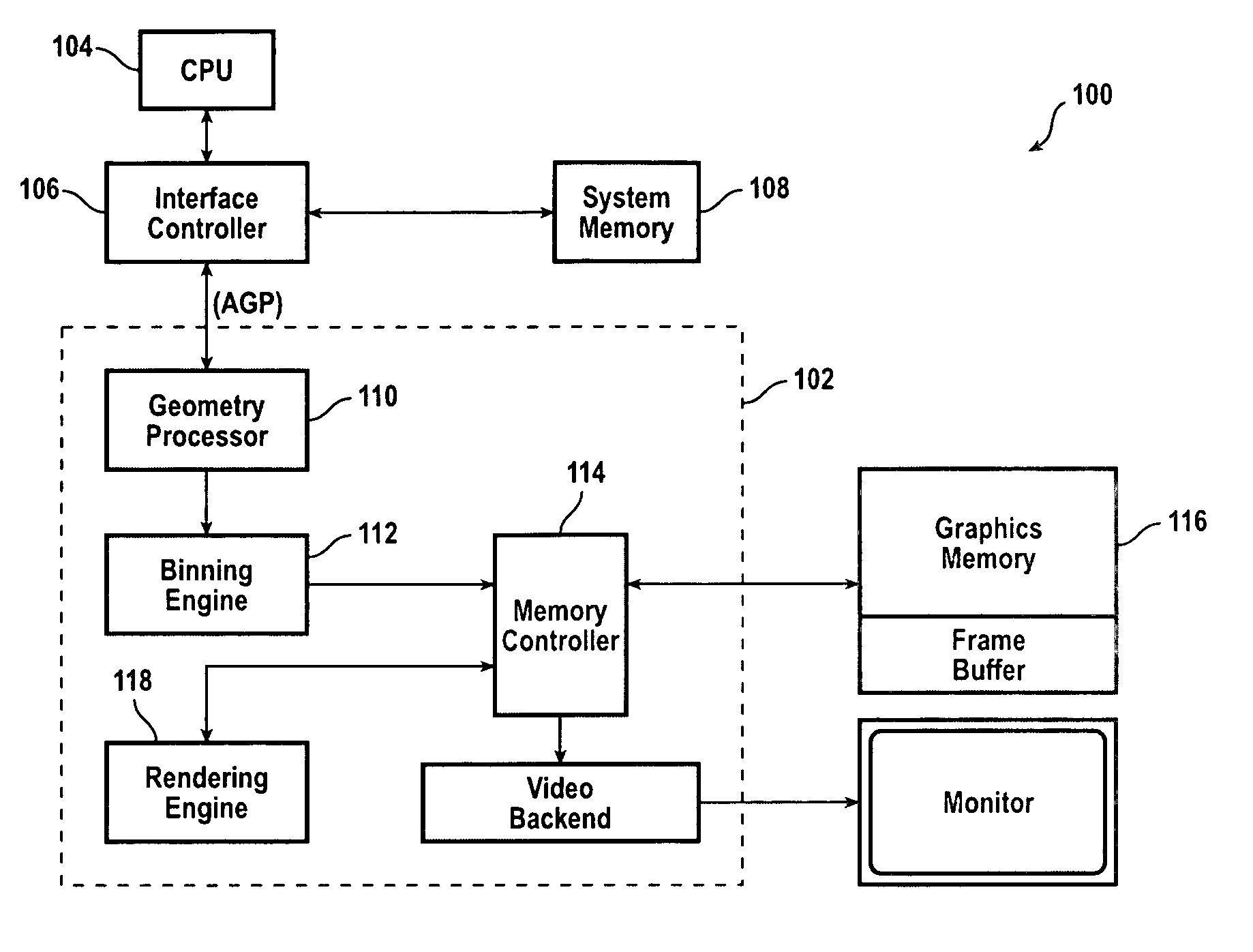
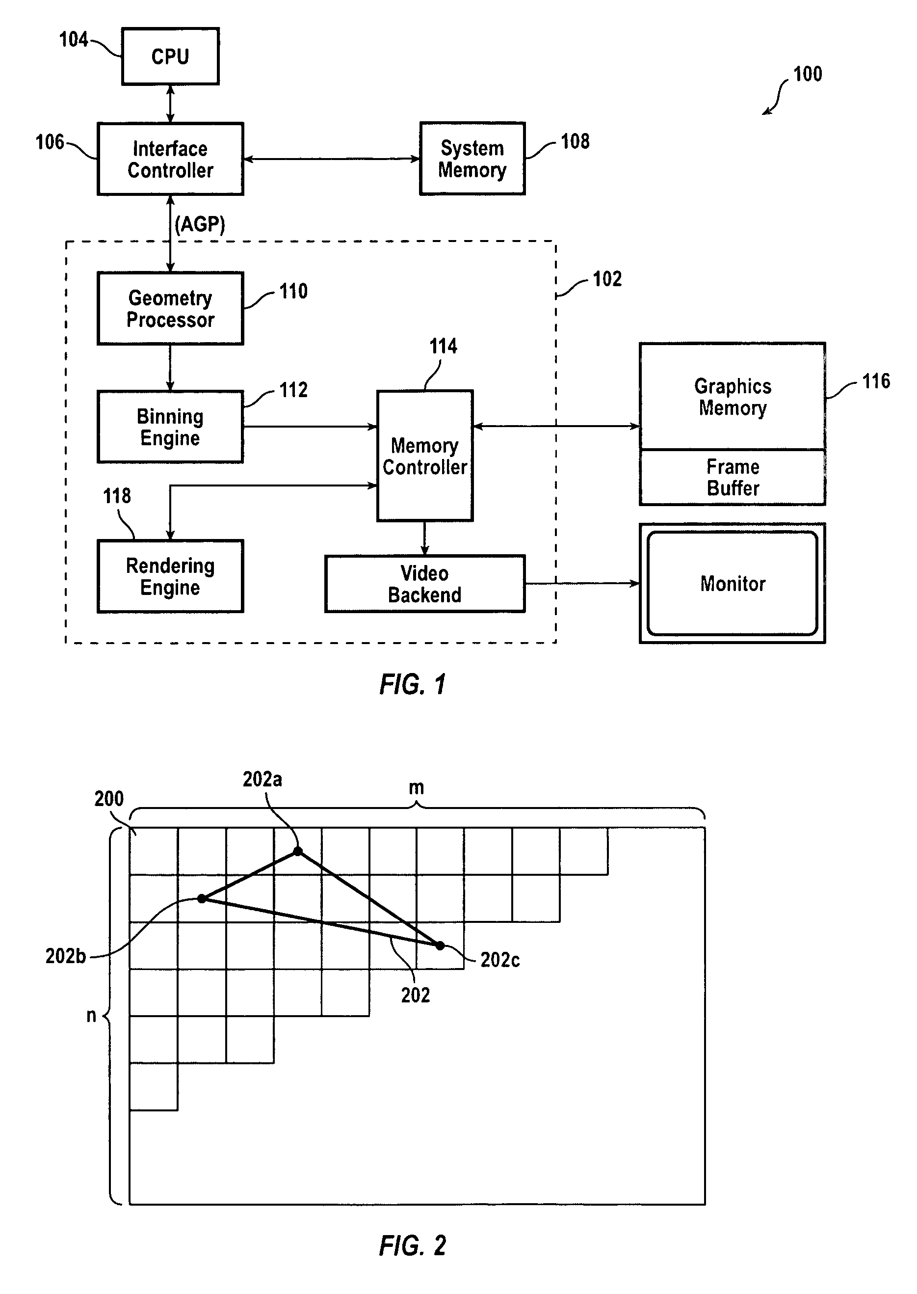
[0021]FIG. 1 is a block diagram of a graphics system 100 that processes graphics data in accordance with an embodiment of the present invention. A graphics processor 102 is coupled to a central processing unit (CPU) 104 by a bus, such as an advanced graphics protocol (AGP) bus, via an interface controller 106. System memory 108 also couples to CPU 104 via interface controller 106. Graphics processor 102 includes a geometry processor 110 that receives graphics data from CPU 104. Graphics data typically includes geometry data and mode data. Geometry data comprises information relating to various polygons (e.g., triangles, parallelograms, rectangles, circles, etc.) which are processed to produce a complete image. Geometry data specifies, for example, the vertices (e.g., in X,Y,Z coordinates) and color (e.g., red-green-blue (RGB)) combinations for various polygons. Mode data comprises information relating to various modes affecting the appearance of one or more geometries when displayed...


PUM


Abstract

A memory system and methods of operating the same that drastically increase the efficiency in memory use and allocation in graphics systems. In a graphics system using a tiled architecture, instead of pre-allocating a fixed amount of memory for each tile, the invention dynamically allocates varying amounts of memory per tile depending on the demand. In one embodiment all or a portion of the available memory is divided into smaller pages that are preferably equal in size. Memory allocation is done by page based on the amount of memory required for a given tile.

Description

CROSS-REFERENCES TO RELATED APPLICATIONS[0001]This application is a continuation of U.S. patent application Ser. No. 09 / 709,964 filed Nov. 10, 2000 now U.S. Pat. No. 6,856,320, which is a continuation-in-part of commonly-assigned U.S. patent application Ser. No. 08 / 978,491, titled “Rendering Pipeline,” by Zhu, filed Nov. 25, 1997 now U.S. Pat. No. 6,697,063. The complete disclosures of these applications are hereby incorporated by reference in their entirety for all purposes.BACKGROUND OF THE INVENTION[0002]The present invention relates in general to memory systems, and in particular to a memory system that provides for efficient use and allocation of memory resources in graphics applications.[0003]Limited memory bandwidth has been a major obstacle in improving the performance of traditional 3-D graphics pipelines. Tiling or “chunking” has evolved as an alternative architecture that reduces the demand on memory bandwidth in 3-D graphics pipelines. A graphics pipeline using tiling ar...

Claims


Application Information

Patent Timeline
IPC IPC(8): G06F13/28G06F12/02G06F12/06
CPCG06T15/005G06T1/60G06F12/0215
Inventor RUBINSTEIN, ORENZHU, MING BENJAMIN
Owner NVIDIA CORP
Learn More