Frequency hopping spread spectrum scheme for RFID reader

Active Publication Date: 2006-09-05
INTERMEC IP
View PDF10 Cites 12 Cited by
  • Summary
  • Abstract
  • Description
  • Claims
  • Application Information

AI Technical Summary

Benefits of technology

[0013]The present invention provides a system and method for improving transmission rates in RFID base stations by implementing forced frequency “hops.” In a preferred embodiment of the present invention, the RFID base station is adapted to calculate whether the next transaction can be performed over the current carrier frequency or whether a “hop” to a new carrier frequency should be forced. More particularly, in one embodiment of the present invention, a base station processor (in conjunction with program information stored in a base station memory) is adapted to (i) determine the amount of time available on a particular carrier frequency (e.g., pursuant to FCC regulations, European Telecommunications Standardization Institute

Problems solved by technology

One of the drawbacks associated with traditional FHSS systems is that time is wasted when the transmitter is not transmitting (i.e., when the transmitter is “dwelling”).
This raises the next issue—i.e., transmission/allocation time variance, or whether there is a variance between the time it takes to transmit data and the time allotted (or prescribed) by the common algor

Method used


Image

  • Frequency hopping spread spectrum scheme for RFID reader
  • Frequency hopping spread spectrum scheme for RFID reader
  • Frequency hopping spread spectrum scheme for RFID reader

Examples


Embodiment Construction

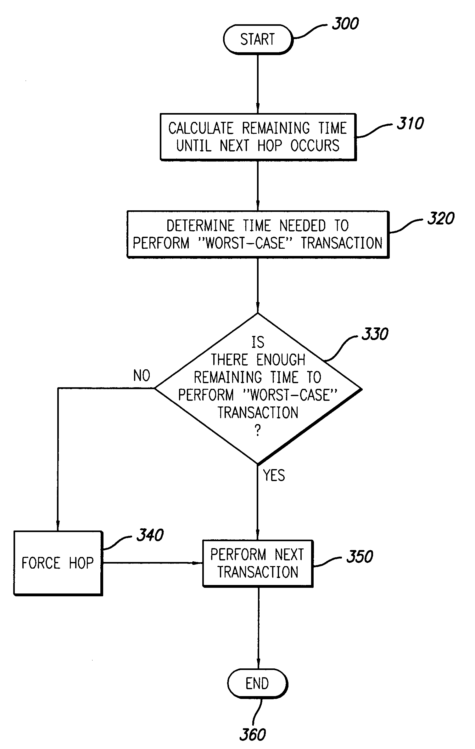
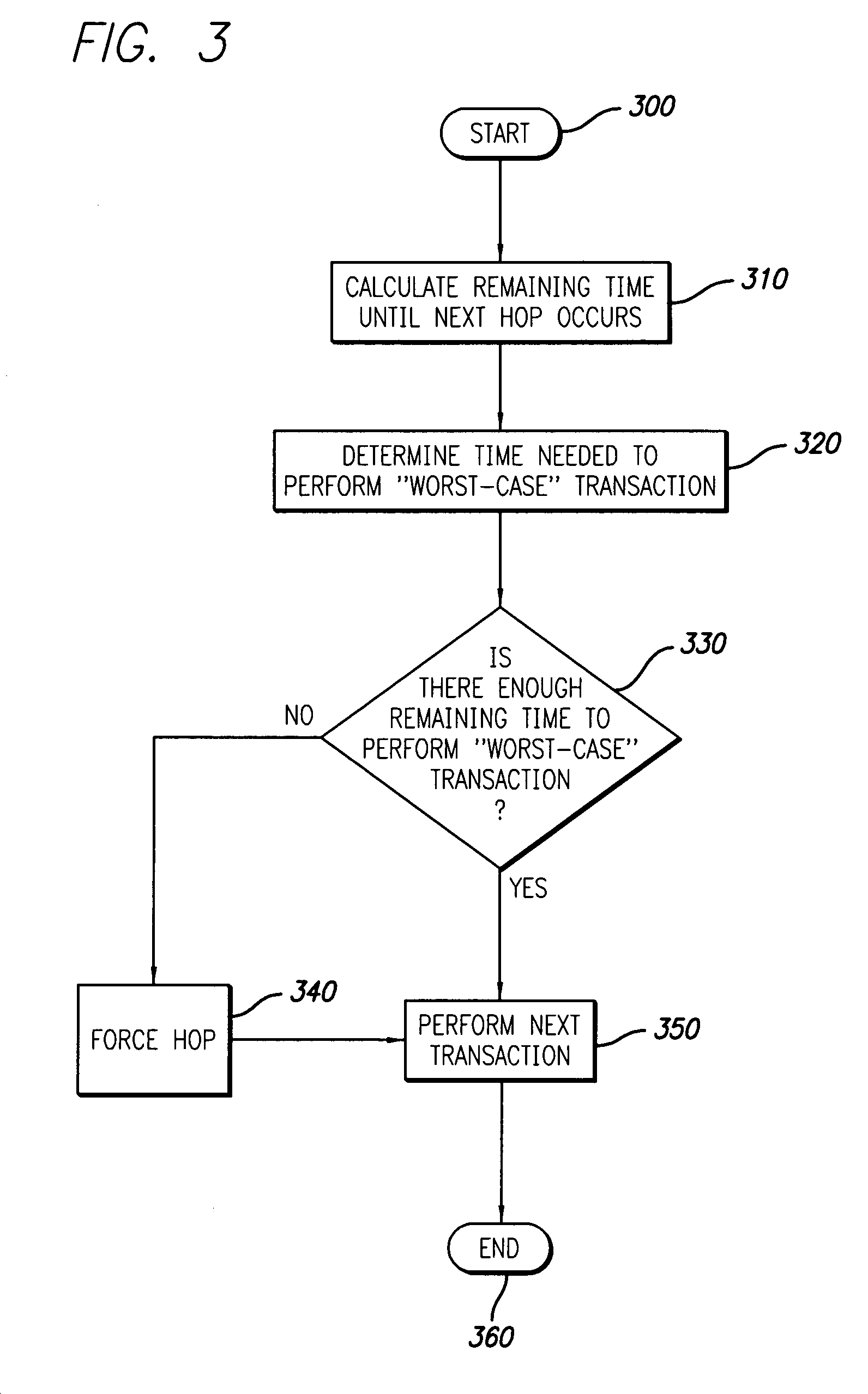
[0019]The present invention provides a system and method for improving transmission rates in RFID base stations by implementing forced frequency “hops.” In the detailed description that follows, like element numerals are used to describe like elements illustrated in one or more figures.

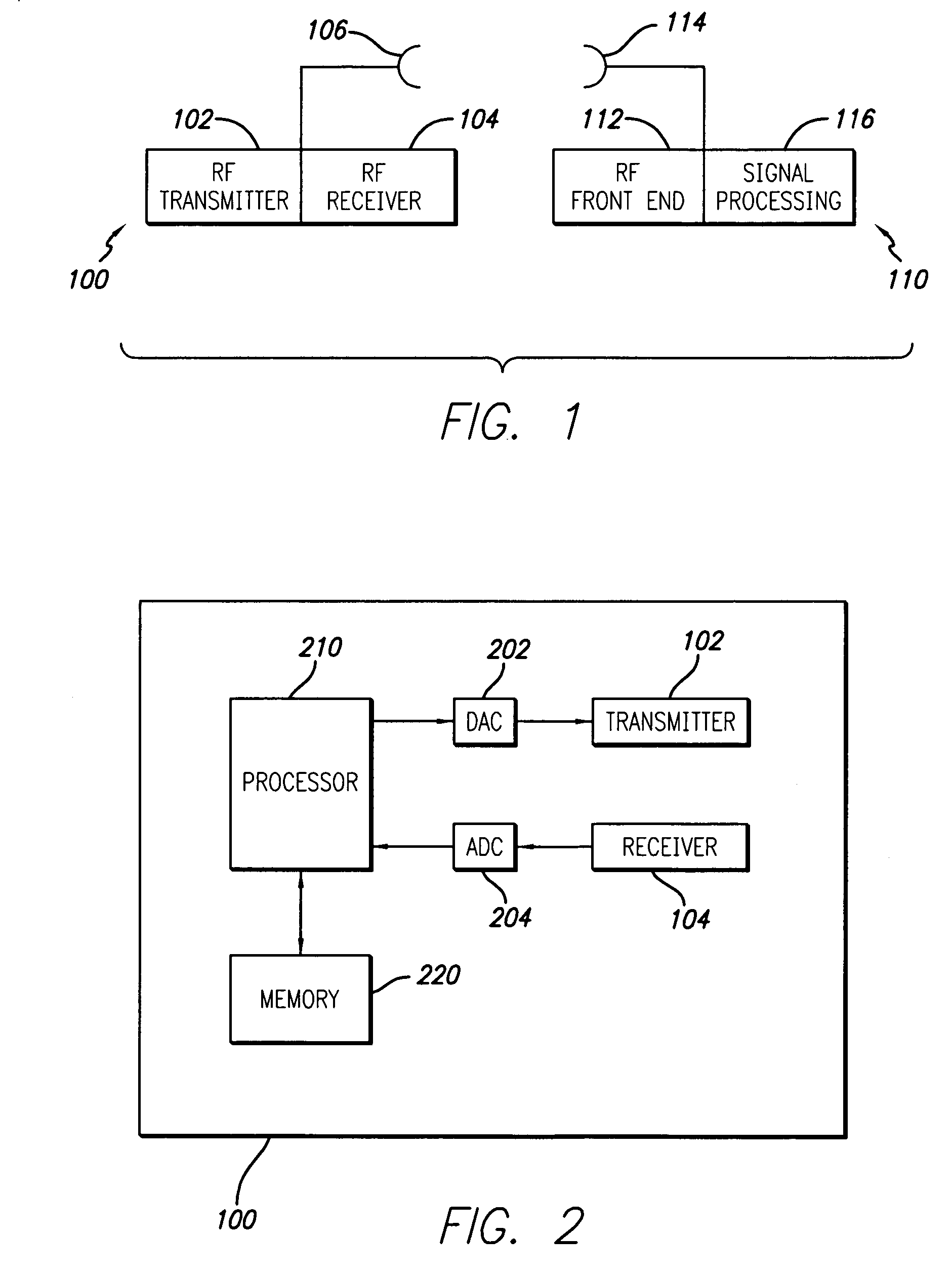
[0020]An RFID system in accordance with the principles of the present invention is illustrated in the conceptual block diagram of FIG. 1. A base station 100 includes (in part) an RF transmitter 102, an RF receiver 104, and an antenna 106 connected to the transmitter 102 and receiver 104. An RFID tag 110 such as may be used in conjunction with the base station 100 includes an RF front end 112, a signal processing section 116, and an antenna 114. The RFID tag 110 may further include a memory (not shown) in which data may be stored, retrieved and / or written.

[0021]In reading the RFID tag 110, the base station 100 interrogates the tag 110 by generating an RF signal over a carrier frequency. The carrier fre...


PUM


Abstract

A system and method is provided for implementing forced frequency “hops” if the time it takes to perform a particular transaction is greater than the time available on a particular carrier frequency. In one embodiment of the present invention, a radio frequency identification (RFID) base station processor (in conjunction with program information stored in a base station memory) is adapted to (i) determine the amount of time available on a particular carrier frequency (e.g., pursuant to Federal Communications Commission (FCC) regulations, European Telecommunications Standardization Institute (ETSI) regulations, etc.), (ii) determine the amount of time it would take to perform a particular transaction, and (iii) force the base station to “hop” to another carrier frequency if the transaction time is longer than the available time. In one embodiment of the present invention, the time it would take to perform a particular transaction is the time it would take to perform the next transaction. In another embodiment of the present invention, the time it would take to perform a particular transaction is the time it would take to perform the longest (or “worst-case”) transaction. In alternate embodiments of the present invention, a transaction is defined as the transmission of information (e.g., data, commands, etc.) or both the transmission of information and the reception of related information.

Description

CROSS-REFERENCE TO RELATED APPLICATION[0001]This application claims benefit pursuant to 35 U.S.C. § 119(e) of U.S. Provisional Application No. 60 / 459,414 filed Mar. 31, 2003, which application is specifically incorporated herein, in its entirety, by reference.BACKGROUND OF THE INVENTION[0002]1. Field of the Invention[0003]The present invention relates to a frequency hopping spread spectrum (FHSS) scheme for radio frequency identification (RFID) devices, and more particularly to a system and method for improving transmission rates in an RFID device by implementing forced frequency “hops.”[0004]2. Description of Related Art[0005]Radio Frequency Identification (RFID) base stations, which operate in conjunction with RFID transponders (tags), are used in a variety of applications (e.g., inventory-control, security, etc.). Typically, an item including an RFID tag (e.g., a container with an RFID tag inside) is brought into a “read zone” established by the base station. The base station tra...

Claims


Application Information

Patent Timeline
IPC IPC(8): H04B1/713H04B7/208H04J1/00H04L5/14G06K7/00
CPCG06K7/0008G06K17/00
Inventor EASTBURN, DAVID LEE
Owner INTERMEC IP
Why Eureka
Try Eureka