Adjustable variable frequency starter/generator system

a starter/generator system and variable frequency technology, applied in the direction of engine starters, electric generator control, gearing, etc., can solve the problems of increasing maintenance costs, increasing cost, weight and complexity of starter/generator systems, and reducing aircraft reliability

Active Publication Date: 2006-09-12
HAMILTON SUNDSTRAND CORP
View PDF36 Cites 23 Cited by
  • Summary
  • Abstract
  • Description
  • Claims
  • Application Information

AI Technical Summary

Problems solved by technology

Furthermore, such pneumatic starter supply systems are complex, and such complexity reduces the reliability of the aircraft and increases maintenance costs.
The use of such high-power motor controllers and power conversion equipment increases cost, weight and complexity of the starter / generator system and it reduces reliability.
This increases cost, weight and complexity of the system.

Method used


Image

  • Adjustable variable frequency starter/generator system
  • Adjustable variable frequency starter/generator system
  • Adjustable variable frequency starter/generator system

Examples


Embodiment Construction

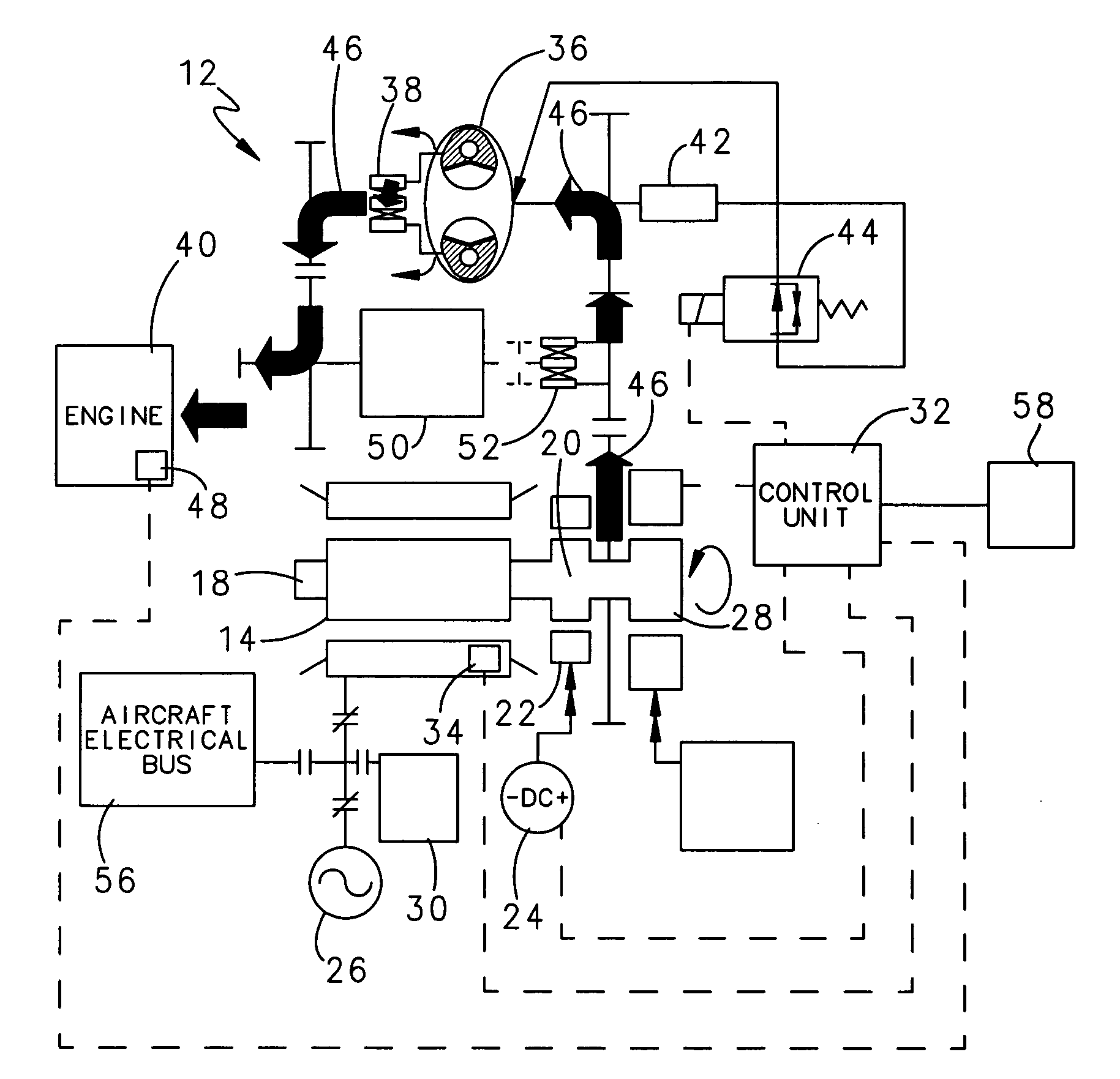
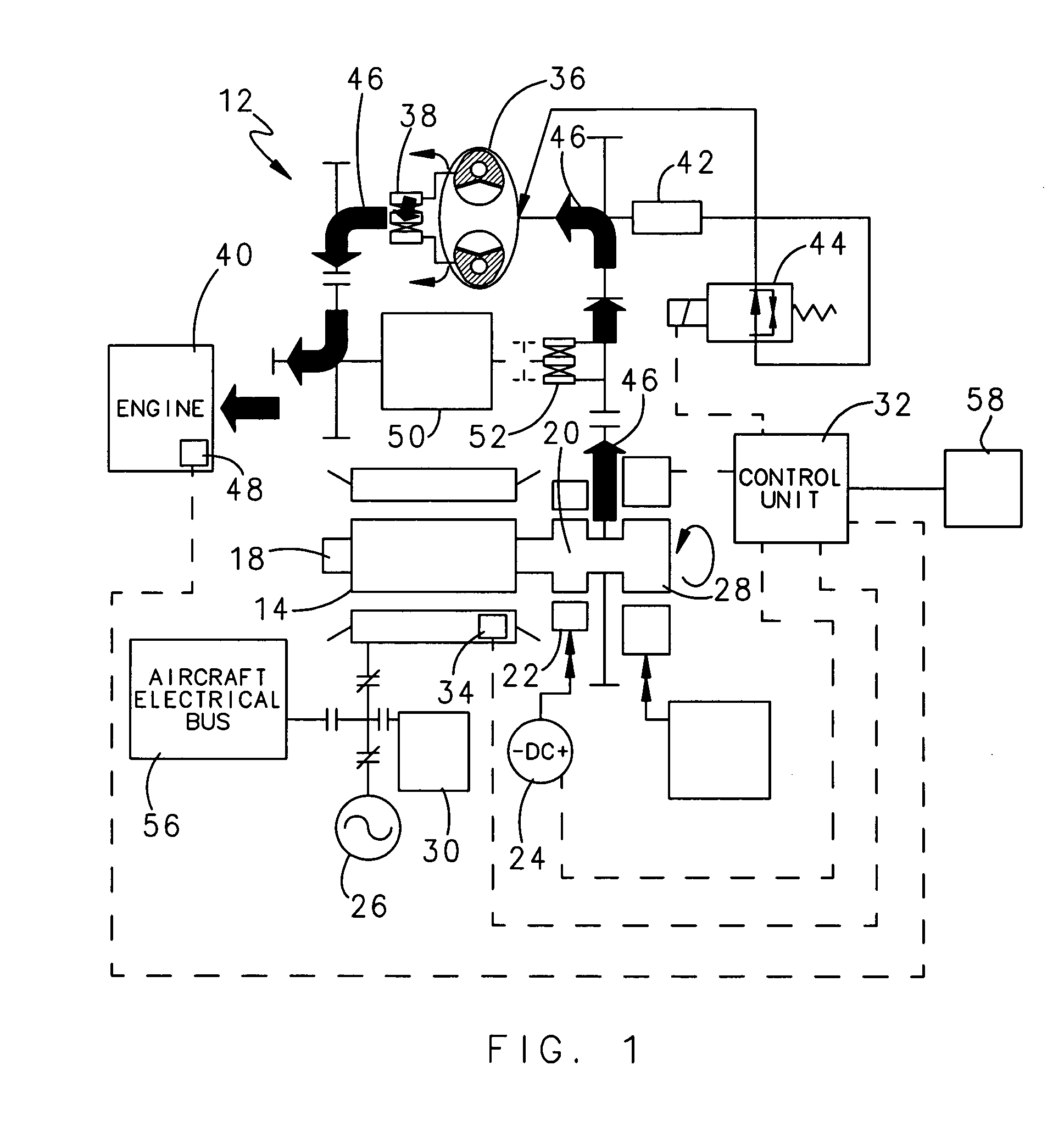
[0015]FIG. 1 is a schematic representation of a starter / generator system 12 according to a preferred embodiment of the invention, showing the flow of mechanical power in an engine-starting mode. A dynamoelectric machine 14 serves as both a starter and generator in the starter / generator system 12. Application of alternating current power to a stator 16 of the dynamoelectric machine 14 creates a rotating magnetic field that rotates a rotor 18 of the dynamoelectric machine 14 when a rotor field is provided by an exciter 20 with an exciter stator 22 that is energised by a suitable low power DC source 24. The alternating current power so supplied to the stator 16 is supplied by a suitable high power external AC source 26, such as a ground cart, auxiliary power unit (APU), or a generator of another engine.

[0016]Before AC from the external AC source 26 is applied to the stator 16, the rotor 18 is preferably brought up to speed to rotate at approximately the angular velocity of the rotating...


PUM


Abstract

A starter / generator system for a gas turbine engine used in aeronautical applications that couples a single dynamoelectric machine to the gas turbine engine through a torque converter in a starting mode, and then disengages the torque converter and engages the engine to the dynamoelectric machine through an adjustable speed transmission in a generating mode after the engine reaches self-sustaining speed, wherein the speed of the adjustable speed transmission is set to match the frequency of AC generated by the dynamoelectric machine with on-board electrical equipment requirements to suit flight conditions.

Description

FIELD OF THE INVENTION[0001]The invention relates to aeronautical electrical systems that comprise a dynamoelectric machine used for starting a gas turbine engine as well as generating electrical power, and more particularly to aeronautical electrical systems that use such a dynamoelectric machine in an adjustable variable frequency configuration.BACKGROUND OF THE INVENTION[0002]Many aircraft that use gas turbine engines for propulsion have commonly used pneumatic starters. Such aircraft have an accessory turbine air motor coupled to each propulsion engine through a gearbox with reduction gearing to crank the propulsion engine.[0003]Compressed air, supplied by a load compressor that is part of an on-board auxiliary power unit (APU) or an external ground cart, supplies compressed air to the turbine air motor through a pneumatic starter supply system that requires numerous air ducts, seals and air valves that are bulky and heavy. Furthermore, such pneumatic starter supply systems are ...

Claims


Application Information

Patent Timeline
Patent Type & Authority Patents(United States)
IPC IPC(8): F02N11/04F16H48/22F16H48/26H02K23/60
CPCF02C7/268F02C7/275H02K7/116F02N11/04F02C7/32
Inventor HOPPE, RICHARD J.THOMSON, SCOTT M.TURNER, DOUGLAS J.
Owner HAMILTON SUNDSTRAND CORP
Why Eureka
Try Eureka