AI technical title is built by Patsnap AI team. It summarizes the technical point description of the patent document.
a predictive deconvolution and robust technology, applied in the field of predictive deconvolution methods and systems, can solve the problems of severe mis-estimation of the desired coefficients within the data window, inability to achieve, etc., and achieve the effect of eliminating spatial ambiguities and high-fidelity impulse responses
Inactive Publication Date: 2006-09-12
THE U S A AS REPRESENTED BY THE SEC OF THE NAVY
View PDF12 Cites 24 Cited by
Summary
Abstract
Description
Claims
Application Information
AI Technical Summary
This helps you quickly interpret patents by identifying the three key elements:
Problems solved by technology
Method used
Benefits of technology
Benefits of technology
[0014]The Reiterative Minimum Mean-Square Error (RMMSE) predictive deconvolution system and method of the invention provide high-fidelity impulse response estimation compared to other systems such as matched filtering and LS. In one embodiment, the RMMSE estimator reiteratively estimates the MMSE filter for each specific impulse response coefficient by mitigating the interference from neighboring coefficients that is a result of the temporal (i.e. spatial) extent of the transmitted waveform. The result is a robust estimator that adaptively eliminates the spatial ambiguities that occur when a fixed receiver filter is used.
Problems solved by technology
Predictive deconvolution provides a means to obtain the high spatial resolution of a short, high bandwidth pulse without the need for very high peak transmit power, which may not be feasible.
However, upon further inspection one finds that the LS received signal model does not completely characterize the received return signal because it does not account for the convolution of the transmitted waveform with impulse response coefficients x(l) prior to l=0.
The result is that the presence of a significant impulse response coefficient within N−1 samples prior to x(0) can cause severe mis-estimation of the desired coefficients within the data window.
Method used
Image
Click on the blue label to locate the original text in one second.
Reading with bidirectional positioning of images and text.
Examples
Embodiment Construction
[0024]Definitions: The term “convolution” means the process that yields the output response of an input to a linear time-invariant system, such as is described and defined in J. G. Proakis and D. G. Manolakis, Digital Signal Processing: Principles, Algorithms, and Apiplications, 3rd Ed., pp. 75–82, Prentice Hall: Upper Saddle River, N.J. (1996), incorporated herein by reference. The term “deconvolution” as used herein means the process that given the output of a system determines an unknown input signal to the system. See Id. at p. 355, incorporated herein by reference. The term “scatterer” means something in the path of a transmitted waveform that causes a significant reflection (relative to the noise) back to the receiver of the sensor.
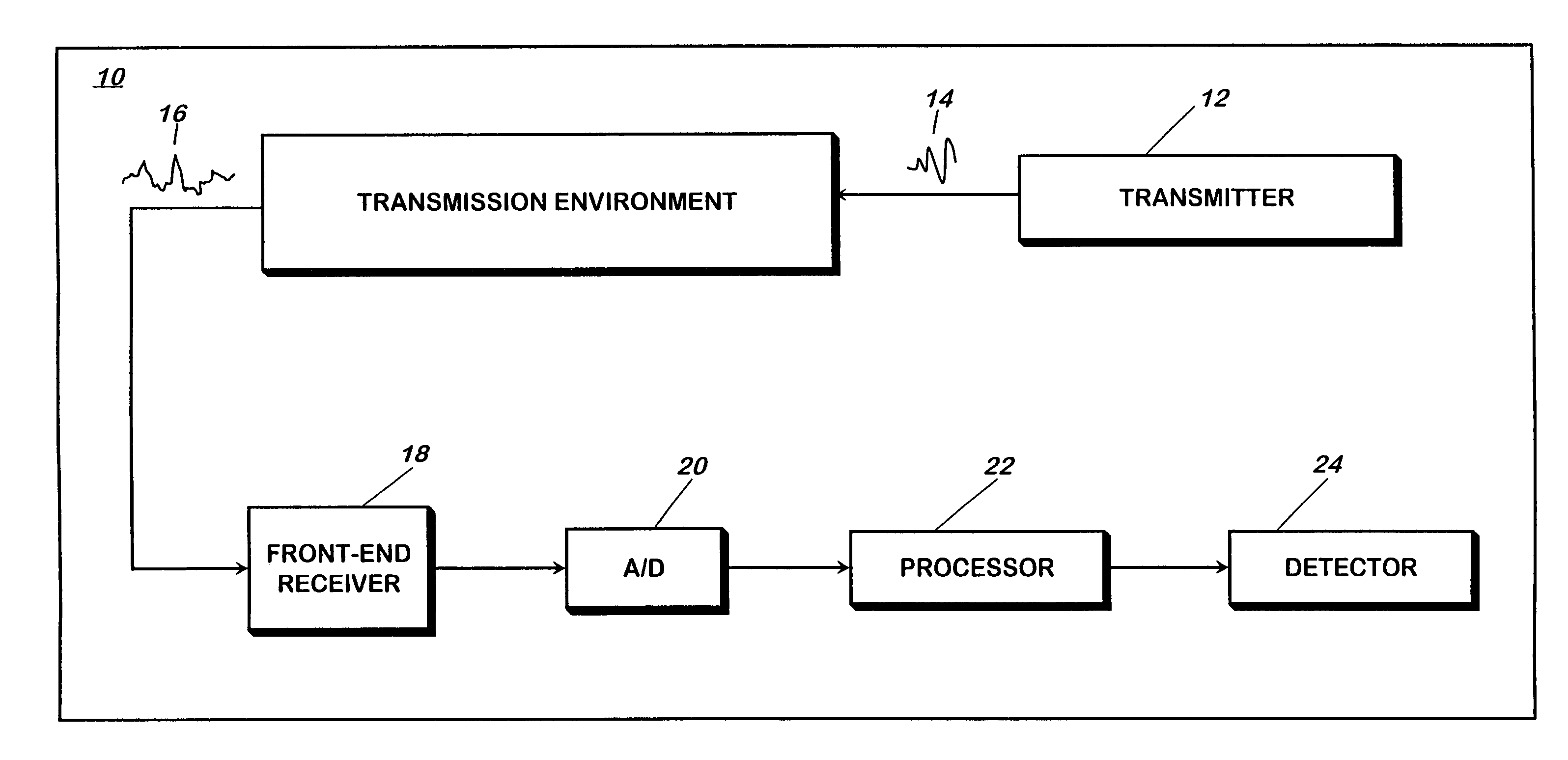
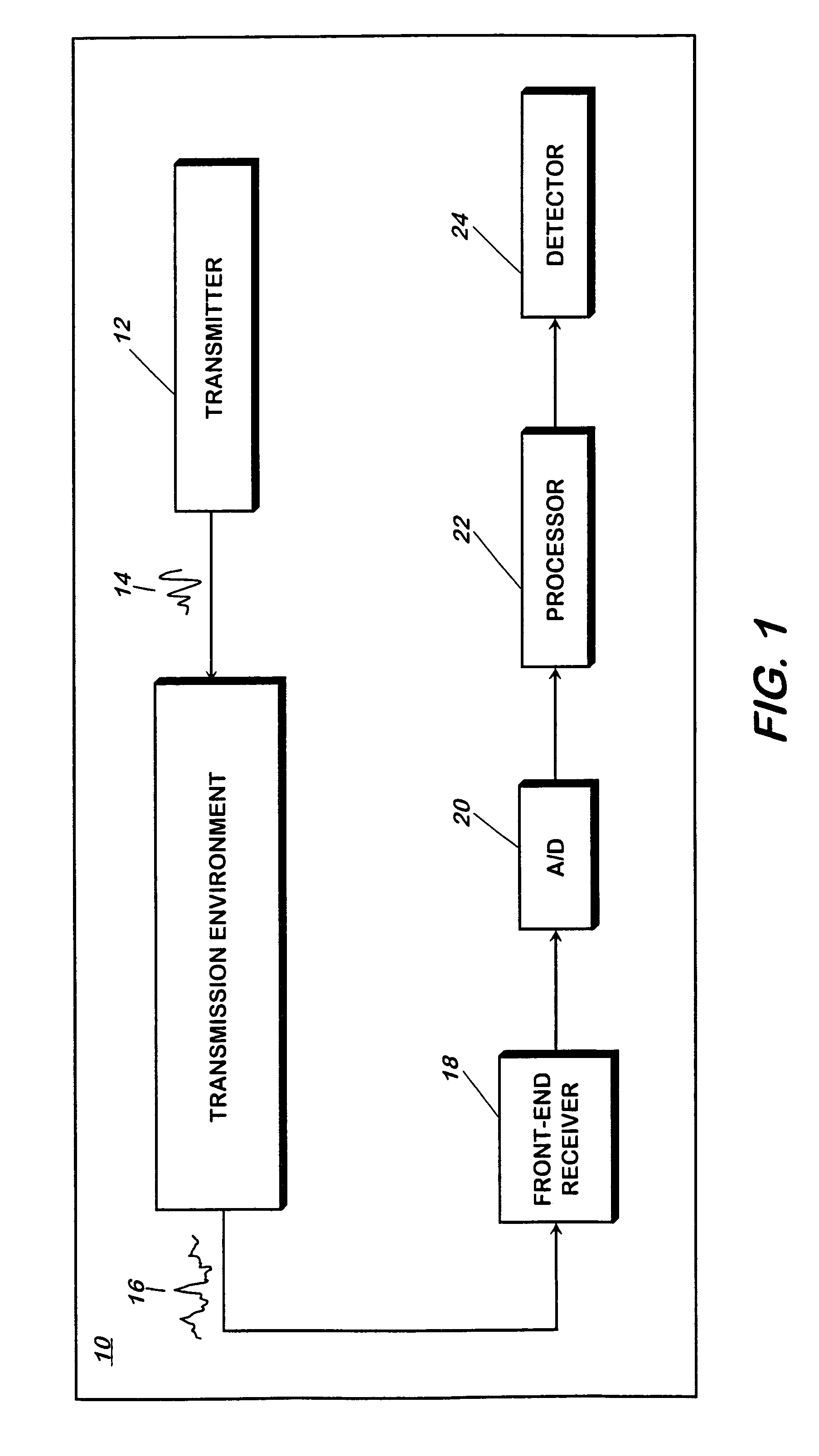
[0025]Referring now to FIG. 1, a predictive deconvolution system 10 includes a transmitter 12 for transmitting a phase or frequency modulated pulse (or waveform) 14 that, upon interacting with its transmission environment's unknown impulse response ...
PUM
Abstract
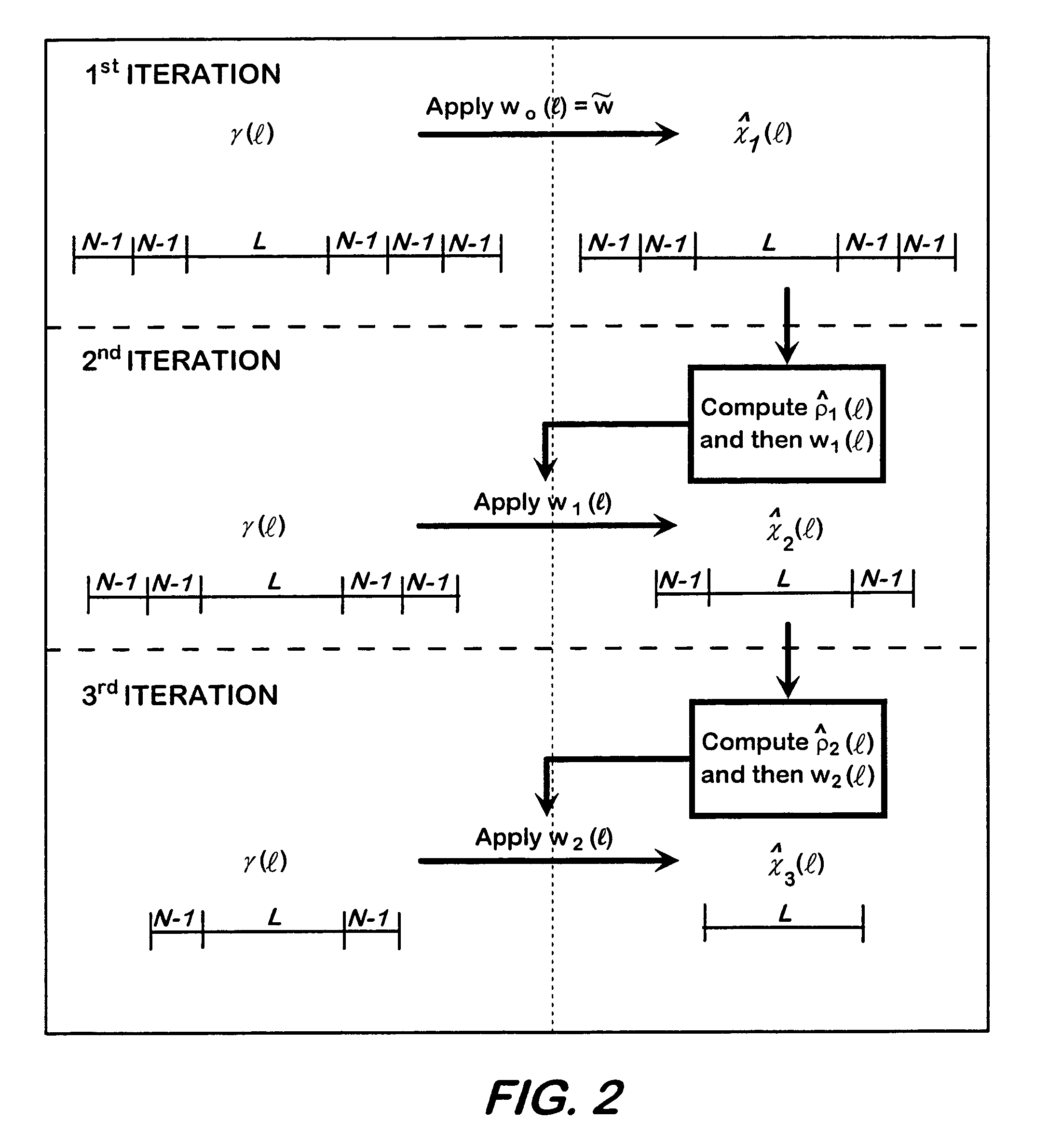
A method for processing a received, modulated pulse (i.e. waveform) that requires predictive deconvolution to resolve a scatterer from noise and other scatterers includes receiving a return signal; obtaining L+(2M−1)(N−1) samples y of the return signal, where y(l)={tilde over (x)}T(l) s+v(l); applying RMMSE estimation to each successive N samples to obtain initial impulse response estimates [{circumflex over (x)}1{−(M−1)(N−1)}, . . . , {circumflex over (x)}1{−1}, {circumflex over (x)}1 {0}, . . . , {circumflex over (x)}1{L−1}, . . . , {circumflex over (x)}1{L}, {circumflex over (x)}1{−1 +(M−1)(N−1)}]; computing power estimates {circumflex over (ρ)}1(l)=|{circumflex over (x)}1(l)|α for l=−(M−1)(N−1), . . . , L−1+(M−1)(N−1) and 0<α≦2; computing MMSE filters according to w(l)=ρ(l) (C(l)+R)−1s, where ρ(l)=E[|x(l)|α] is the power of x(l), for 0<α≦2, and R=E[v(l) vH(l)] is the noise covariance matrix; applying the MMSE filters to y to obtain [{circumflex over (x)}2{−(M−2)(N−1)}, . . . , {circumflex over (x)}2{−1}, {circumflex over (x)}2{0}, . . . , {circumflex over (x)}2{L−1}, {circumflex over (x)}2{L}, . . . , {circumflex over (x)}2{L−1+(M−2)(N−1)}]; and repeating (d)–(f) for subsequent reiterative stages until a desired length-L range window is reached, thereby resolving the scatterer from noise and other scatterers. The RMMSE predictive deconvolution approach provides high-fidelity impulse response estimation. The RMMSE estimator can reiteratively estimate the MMSE filter for each specific impulse response coefficient by mitigating the interference from neighboring coefficients that is a result of the temporal (i.e. spatial) extent of the transmitted waveform. The result is a robust estimator that adaptively eliminates the spatial ambiguities that occur when a fixed receiver filter is used.
Description
[0001]This application is a continuation-in-part of U.S. application Ser. No. 10 / 673,343 entitled “ROBUST PREDICTIVE DECONVOLUTION SYSTEM AND METHOD”, filed on Sep. 30, 2003, now U.S. Pat. No. 6,940,450 which claims priority from U.S. Provisional Patent Application Ser. No. 60 / 499,372, filed on Sep. 3, 2003, the disclosures of both of which are hereby incorporated by reference.FIELD OF THE INVENTION[0002]This invention relates to a method and system for predictive deconvolution, which is otherwise known as pulse compression in radar applications. More particularly, the invention relates to robust predictive deconvolution using minimum mean-square error reiteration.BACKGROUND OF THE INVENTION[0003]In many sensing applications, such as radar pulse compression, sonar, ultrasonic non-destructive evaluation for structural integrity, biomedical imaging, and seismic estimation, it is desirable to estimate the impulse response of an unknown system by driving the system with a known signal h...
Claims
Application Information
Patent Timeline
Application Date:The date an application was filed.
Publication Date:The date a patent or application was officially published.
First Publication Date:The earliest publication date of a patent with the same application number.
Issue Date:Publication date of the patent grant document.
PCT Entry Date:The Entry date of PCT National Phase.
Estimated Expiry Date:The statutory expiry date of a patent right according to the Patent Law, and it is the longest term of protection that the patent right can achieve without the termination of the patent right due to other reasons(Term extension factor has been taken into account ).
Invalid Date:Actual expiry date is based on effective date or publication date of legal transaction data of invalid patent.

