System and method for rendering digital images having surface reflectance properties

a technology of surface reflectance and system method, applied in the field of computer generated graphical images, can solve the problems of affecting the effect of image quality,

Inactive Publication Date: 2006-09-12
HEWLETT PACKARD DEV CO LP
View PDF7 Cites 18 Cited by
  • Summary
  • Abstract
  • Description
  • Claims
  • Application Information

AI Technical Summary

Problems solved by technology

Such calculations are usually time-consuming and expensive whether performed in hardware or software.
Unfortunately, such methods also usually fail to render shading features that are smaller than the areas of individual polygons.
If the polygons are relatively large, the view will be noticeably distorted.
However, this approach is limited as the final graphical image, to an extent, appears flat.
Existing techniques for rendering of BRDFs have typically been computationally inefficient, thereby resulting in relatively slow rendering of graphical images having reflectance properties.

Method used


Image

  • System and method for rendering digital images having surface reflectance properties
  • System and method for rendering digital images having surface reflectance properties
  • System and method for rendering digital images having surface reflectance properties

Examples


Embodiment Construction

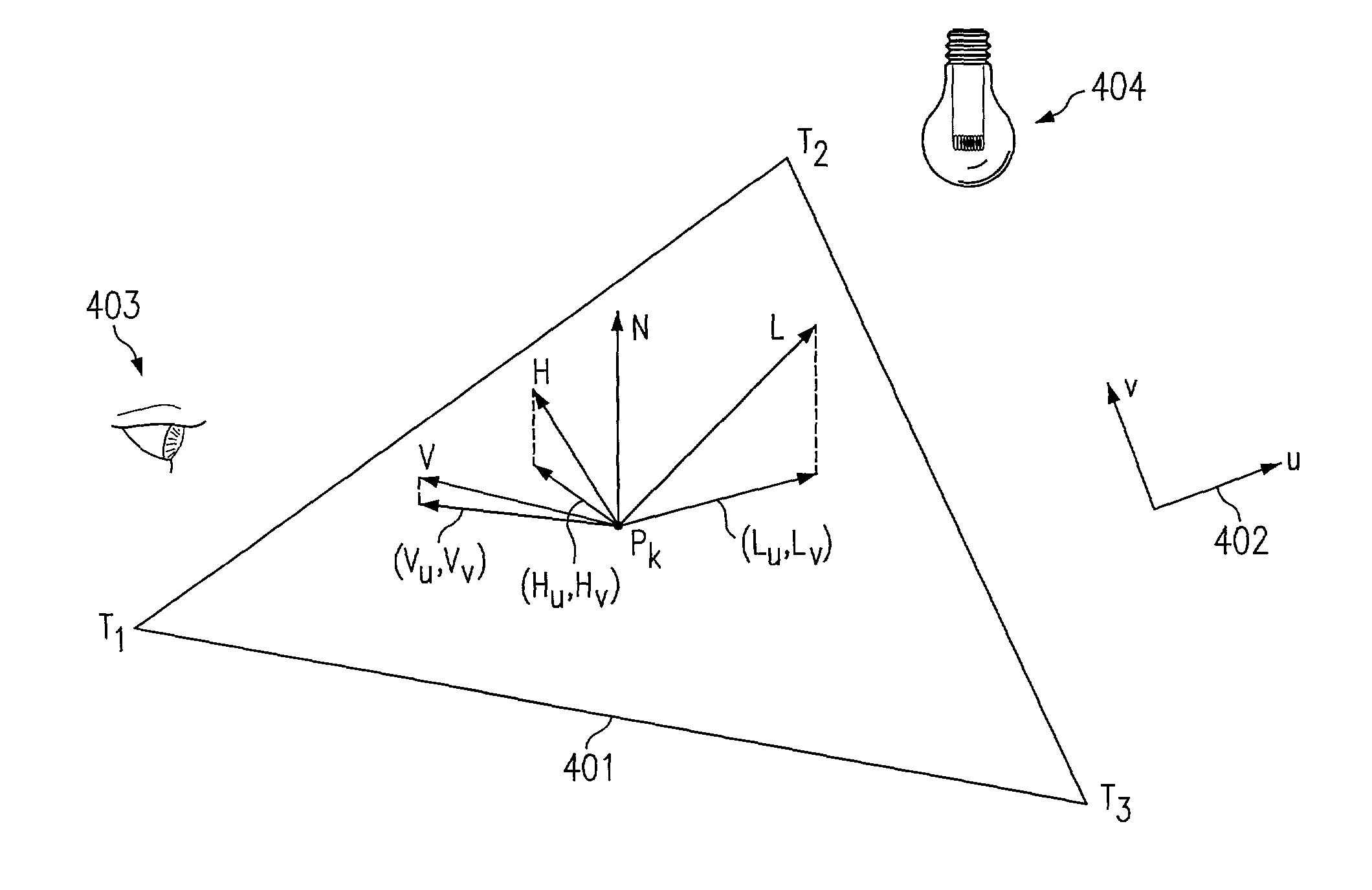
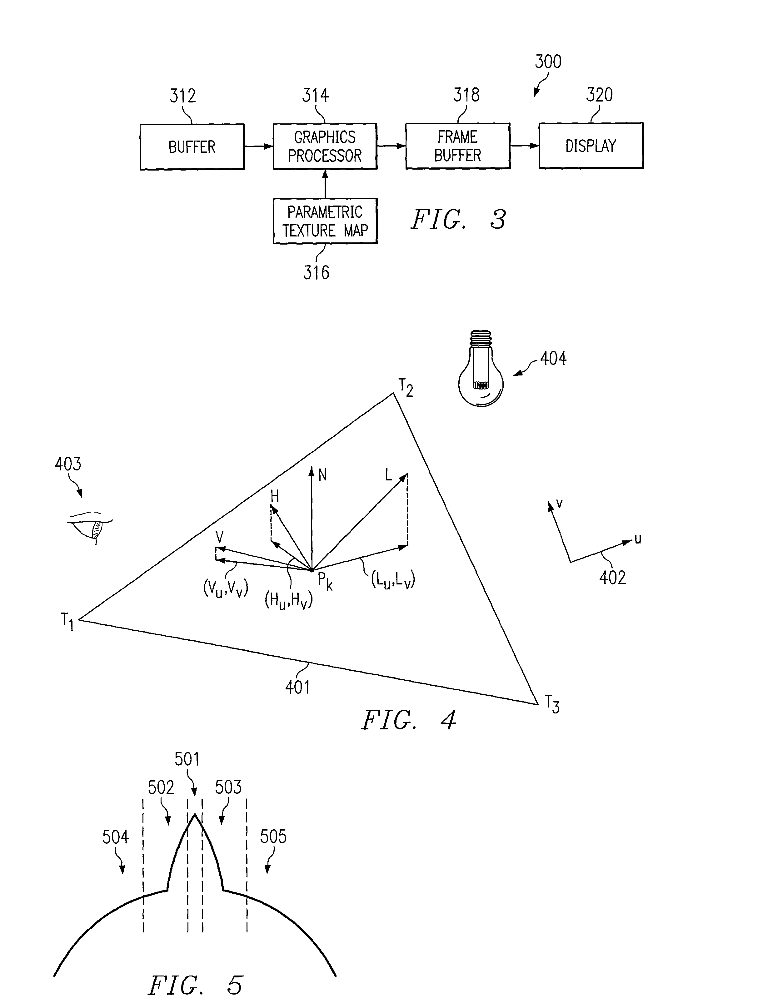
[0030]In general, texture mapping has gained much appreciation because of the computational efficiency of many texture mapping techniques in rendering graphical images. That is, many texture mapping techniques are computationally more efficient than non-texture mapping techniques, such as very complex geometry techniques (e.g., using very many tiny triangles) and radiosity (ray-traced lighting algorithms). Thus, because of their computational efficiency, texture mapping techniques may enable graphical images to be rendered much more quickly than non-texture mapping techniques. As described above, bump mapping is one texture mapping technique. More recently, another technique, known as parametric texture mapping (“PTM”), has been developed for performing texture mapping in a manner that renders greater realism than the bump mapping technique.

[0031]In general, PTM, which is described further below, is a computer algorithm for rendering objects using a 2D representation of light. PTM p...


PUM


Abstract

According to one embodiment of the present invention, a method for rendering a digital image having surface reflectance properties is disclosed. The method comprises creating a parametric texture map that comprises parameters for an equation that defines a surface structure in a manner in which the appearance of the surface structure includes surface reflectance properties. The method further comprises rendering a digital image using the parametric texture map.

Description

RELATED APPLICATIONS[0001]This application is related to co-pending and commonly assigned U.S. patent application Ser. No. 09 / 528,700 filed Mar. 17, 2000, entitled “APPARATUS FOR AND METHOD OF RENDERING 3D OBJECTS WITH PARAMETRIC TEXTURE MAPS,” and co-pending and commonly assigned U.S. patent application Ser. No. 09 / 527,872 filed Mar. 17, 2000, entitled “APPARATUS FOR AND METHOD OF ENHANCING SHAPE PERCEPTION WITH PARAMETRIC TEXTURE MAPS,” the disclosures of which are hereby incorporated herein by reference.TECHNICAL FIELD[0002]The present invention relates in general to computer-generated graphical images, and more specifically to a system and method for rendering digital images having surface reflectance properties.BACKGROUND[0003]Computer graphics systems are commonly employed for rendering graphical images. Conventional computer graphics systems commonly include a display device having a two-dimensional (2D) array of light emitting areas. The light emitting areas are usually refe...

Claims


Application Information

Patent Timeline
Patent Type & Authority Patents(United States)
IPC IPC(8): G06T15/50G06T15/04
CPCG06T15/506G06T15/04
Inventor RITTER, BRADFORD A.GELB, DANIEL G.MALZBENDER, THOMAS
Owner HEWLETT PACKARD DEV CO LP
Why Eureka
Try Eureka