Backlight unit in a liquid crystal display device

a liquid crystal display device and backlight technology, applied in the field of backlight units, can solve the problems of increasing the size and cost of the power supply board or inverter, and the luminance irregularity of the light-emitting surface, and achieve the effects of reducing the luminance irregularity, suitable display quality, and reducing the lighting start voltag

Active Publication Date: 2006-09-12
VISTA PEAK VENTURES LLC
View PDF22 Cites 17 Cited by
  • Summary
  • Abstract
  • Description
  • Claims
  • Application Information

AI Technical Summary

Benefits of technology

[0015]An object of the present invention is to provide a direct-irradiation type backlight unit capable of solving the above problems by reducing the luminance irregularity and increasing the luminance efficiency irrespective of whether the backlight unit is configured as a double-sided or single-sided unit. It is also an object of the present invention to provide a backlight unit in which the lighting start voltage can be lowered even when the backlight unit is disposed in a dark state or low temperature state during the operating time thereof.
[0019]The backlight unit according to the first aspect of the present invention is capable of reducing the luminance irregularity observed on the light-emitting surface irrespective of whether the backlight unit is a double-sided emission type or single-sided emission type. Therefore, a suitable display quality can be realized in the LCD device having the backlight unit according to the first aspect of the present invention.
[0020]The LCD device having the backlight unit according to the second aspect of the present invention is capable of allowing the lamp to be turned on at a lower lighting start voltage even in the case of a dark state or low temperature state of the backlight unit, thereby reducing the cost of the lamp drive circuit of the backlight unit.

Problems solved by technology

This leads to an increase in the size and cost of a power supply board, or inverter 219, for supplying the electric power to the lamp 213.
In this case, there arise a problem in that a luminance irregularity is observed on the light-emitting surface of the backlight unit 201.

Method used


Image

  • Backlight unit in a liquid crystal display device
  • Backlight unit in a liquid crystal display device
  • Backlight unit in a liquid crystal display device

Examples


first embodiment

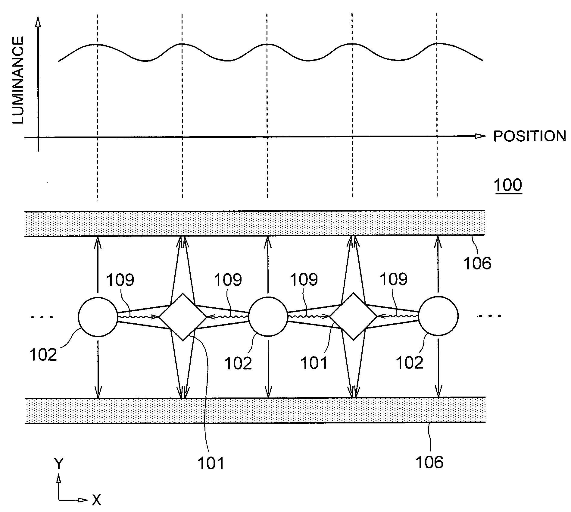
[0040]The scatter-reflection rod member 101 is disposed such that the cross-sectional center thereof is set at the position that divides the line segment connecting the respective centers of the two adjacent lamps 102 equally. The adjacent two lamps 213 shown in FIG. 16 illuminate each other in the conventional double-sided backlight unit 204, whereas the scatter-reflection rod member 101 reflects and scatters the light emitted from the lamps 102 by the scatter-reflection surface thereof, with the result that the light travels in the direction toward the front- and back-side diffusion plates 106, in the double-sided backlight unit 100 of the

[0041]As shown in the graph of FIG. 1, the observed luminance on the front- and rear-side diffusion plates 106 changes depending on the position in X-direction. More specifically, the highest luminance is observed at the position right above the center of the lamp 102 and that right above the center of the scatter-reflection rod member 101. This ...

fifth embodiment

[0062]The double-sided backlight unit in which the conical member is formed on the optical rod member for supporting the diffusion plate has been described in the A single-sided backlight unit may have a support member for supporting the diffusion plate between adjacent two of the lamps. The support member may be formed on another member other than the rod member.


PUM

PropertyMeasurementUnit
distanceaaaaaaaaaa
distanceaaaaaaaaaa
alternating voltageaaaaaaaaaa

Abstract

A double-sided, direct-irradiation type backlight unit has a structure of capable of reducing the luminance irregularity and improve the luminance efficiency. The backlight unit has a scatter-reflection rod member 101 between each adjacent two of elongate lamps. The scatter-reflection rod member 101 has a symmetric shape with respect to the line passing the center thereof in X-direction, and that passing the center thereof in Y-direction. The light emitted from the elongate lamp 102 in X-direction is reflected by the scatter-reflection-rod member 101 and then travels in the direction toward the front- and rear-side diffusion plates 106.

Description

BACKGROUND OF THE INVENTION[0001]1. Field of the Invention[0002]The present invention relates to a backlight unit for use in a liquid crystal display device, and more particularly, to a direct-irradiation type backlight unit in which a light source is disposed to oppose a light-emitting surface of the backlight unit.[0003]The present invention also relates to a liquid crystal display device having such a backlight unit.[0004]2. Description of Related Art[0005]A backlight unit for use in a liquid crystal display (LCD) device is roughly classified into two types. One is a direct-irradiation type and the other an edge-light type having an optical guide plate. In the direct-irradiation type backlight unit, a plurality of light sources (lamps) are disposed to oppose a light-emitting surface of the backlight unit. A higher luminance can be easily obtained in the direct-irradiation type backlight unit as compared to the edge-light type backlight unit.[0006]FIG. 10 is an exploded view showi...

Claims


Application Information

Patent Timeline
Patent Type & Authority Patents(United States)
IPC IPC(8): G02F1/13F21S2/00F21V5/02F21Y103/00G02F1/13357
CPCG02F1/133604G02F1/133611G02F2001/133607G02F2001/133342G02F1/133342G02F1/133607A47G27/02A47L23/266
Inventor ONO, SHIN-ICHIROUFUKUYOSHI, HIROKAZU
Owner VISTA PEAK VENTURES LLC
Why Eureka
Try Eureka