Image processing device and method for controlling the same

a technology of image processing and control method, which is applied in the field of image processing device and control method, can solve the problems that excessive un-sharpness processing is required, the effect of suppressing the appearance of moir

Inactive Publication Date: 2006-09-12
KK TOSHIBA +1
View PDF5 Cites 9 Cited by
  • Summary
  • Abstract
  • Description
  • Claims
  • Application Information

AI Technical Summary

Benefits of technology

[0010]An object of the present invention is to provide an image processing device and a method for controlling the same, in order to overcome the above-described problematic points, by making it possible to select a filter factor which has appropriate frequency characteristics in accordance with the sampling rate and a processing flow of an input image signal, thus moire can be suppressed without the need for an excessive un-sharpness processing.

Problems solved by technology

Thus, functions such as elimination of moire and the like cannot be realized with the same filter factor.
Thus, a separate, excessive un-sharpness processing is required, and the problem arises that this is not always preferable from the standpoint of cost performance.

Method used


Image

  • Image processing device and method for controlling the same
  • Image processing device and method for controlling the same
  • Image processing device and method for controlling the same

Examples


first embodiment

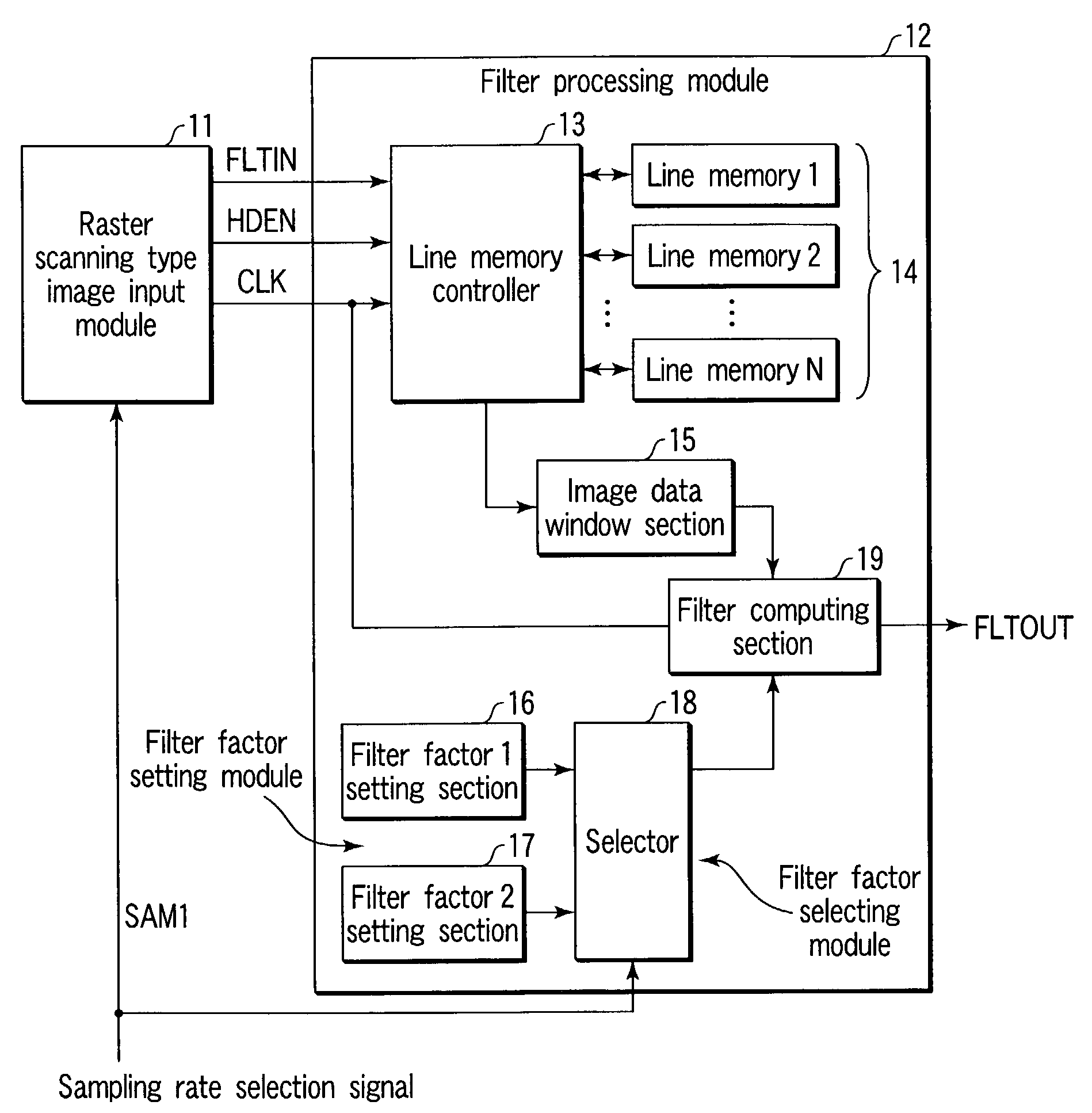
[0089]FIG. 1 is a block diagram showing a schematic configuration in accordance with a first embodiment of the image processing device of the present invention.

[0090]The image processing device is configured from a raster scanning type image input module 11 which reads and outputs an image of an unillustrated manuscript at different sampling rates, and a filter processing module 12 which carries out a filter processing on the image signal which is inputted by the raster scanning type image input module 11.

[0091]At the raster scanning image input module 11, the sampling rate at the time of reading an image of a manuscript is switched by a sampling rate selection signal SAM1 from the exterior.

[0092]Here, the raster scanning type image input module 11 reads the image of the manuscript at a main scanning sampling rate of 600 dpi and a sub-scanning sampling rate of 600 dpi, when SAM1=0 (high sampling rate mode).

[0093]Further, the raster scanning type image input module 11 reads the image...

second embodiment

[0157]Next, an image processing device of a second embodiment of the present invention will be described.

[0158]Note that, because the main configurations of the second embodiment are similar to those of the first embodiment shown in FIG. 1, description thereof is omitted.

[0159]In a printed photograph or an image outputted by a printer or the like, there is a periodic component (called a main frequency component) in the high frequency, other than the frequency component that is generated by a contrast of the original image or the like.

[0160]The frequency of the frequency component is (fpx, fpy), and fp=∥(fpy, fpx)∥—2. (Namely, the absolute value of the main frequency component is, for convenience, called the main frequency component.)

[0161]Note that, ∥a∥—2 means square norm sqrt (a^2)

[0162]In the present embodiment, the main frequency component is a design parameter, and determines the frequency characteristic of the filter factor 1 and the frequency characteristic of the filter fact...

first modified example

OF THE SECOND EMBODIMENT

[0176]Further, in the second embodiment as described above, the main frequency component is (fpx, fpy). However, as a first modified example of the second embodiment, it suffices that the number of screen lines of the manuscript image is used instead of the main frequency component (fpx, fpy) in the filter processing relating to read image data of a manuscript which is screen-printed.


PUM


Abstract

An image input module inputs image signals which have different sampling rates. Based on a predetermined processing flow, a filter processing module carries out a filter processing by a predetermined filter factor on the image signals which are inputted by the image input module. A plurality of filter factors which are used at the filter processing module are set at a filter factor setting module. A filter factor selecting module selects, from among a plurality of filter factors, an appropriate filter factor in accordance with the sampling rates of the image signals and the processing flow, and supplies them to the filter processing module.

Description

BACKGROUND OF THE INVENTION[0001]1. Field of the Invention[0002]The present invention relates to an image processing device and a method for controlling the same, and in particular, to an image processing device and a method for controlling the same which employ a technique which is applied to filter processing in an image processing section of an image forming device, such as a color image copier or the like, which handles image signals of different sampling rates.[0003]2. Description of the Related Art[0004]In a conventional color image copier, three-channel image signals such as RGB signals are read out by a charge coupled device (CCD) or the like at the same sampling rate, and are processed in an image processing section at a latter stage.[0005]Thus, at a filter included in the image processing section, frequency characteristics, such as a cut-off frequency and the like, which are appropriate for only that sampling rate are set.[0006]Moreover, when a line sensor (CCD), which out...

Claims


Application Information

Patent Timeline
Patent Type & Authority Patents(United States)
IPC IPC(8): H04N1/407G06T5/20H04N1/00H04N1/04H04N1/409
CPCG06T5/20G06T5/002H04N1/4092H04N1/0402G06T2207/10008
Inventor TAKANO, GAKU
Owner KK TOSHIBA
Why Eureka
Try Eureka