Device for protecting against voltage surges

a technology for devices and voltage surges, applied in the direction of resistors, emergency protective arrangements for limiting excess voltage/current, non-adjustable resistors, etc., can solve the problems of reducing the protection, reducing the protection, and deteriorating of the electronic apparatus

Inactive Publication Date: 2006-09-12
ADEE ELECTRONICS
View PDF13 Cites 49 Cited by
  • Summary
  • Abstract
  • Description
  • Claims
  • Application Information

AI Technical Summary

Benefits of technology

[0025]Interestingly, the connection between the metal ring and the outer tube is ensured by welding spots whose volume and number are such that they are adapted to melt under the effect of a voltage surge so as to perform a function of disconnector.

Problems solved by technology

However, these latter possess noteworthy drawbacks and in particular that of presenting a considerable delay at ignition so that, in certain cases, and especially in the case of particularly violent and rapid voltage surges provoked by lightning, the electronic apparatus deteriorate before the lightning current is diverted by the discharge arrester.
Now, the principal drawback of varistors is that, under the effect of repeated electric shocks, and by reason of the high operational temperatures, they are subjected to wear which is translated by a resistive fast-blow by lowering of the peak-clipping threshold.
One of the disconnectors used is obligatorily disposed inside the body of the lightning arrester, which brings about elimination of the protection as soon as it is actuated.
Such a mode of operation is extremely risky at the level of protection of an installation insofar as, during a storm, the voltage surges follow one another at a certain rhythm depending on the different thunder claps.
It is also known that another drawback of the varistors is that they present too high a residual voltage in the case of a very rapid voltage front and in the case of very strong currents.
These lightning arresters are such that, once the Zener diode is destroyed due to a voltage surge, they immediately become conducting, with the result that they conduct the voltage surge to earth.
In that case they present a considerable capacity of flow of the currents and very weak residual voltages, and this in all cases.
Unfortunately, lightning arresters of this type present the drawback of being of a high cost, insofar as the Zener diodes used are constructed from monocrystalline silicon which is much more expensive than the products used for producing the varistors and which must be disposed between heat-dissipating discs made of copper or silver.

Method used


Image

  • Device for protecting against voltage surges
  • Device for protecting against voltage surges

Examples


Embodiment Construction

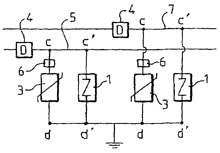
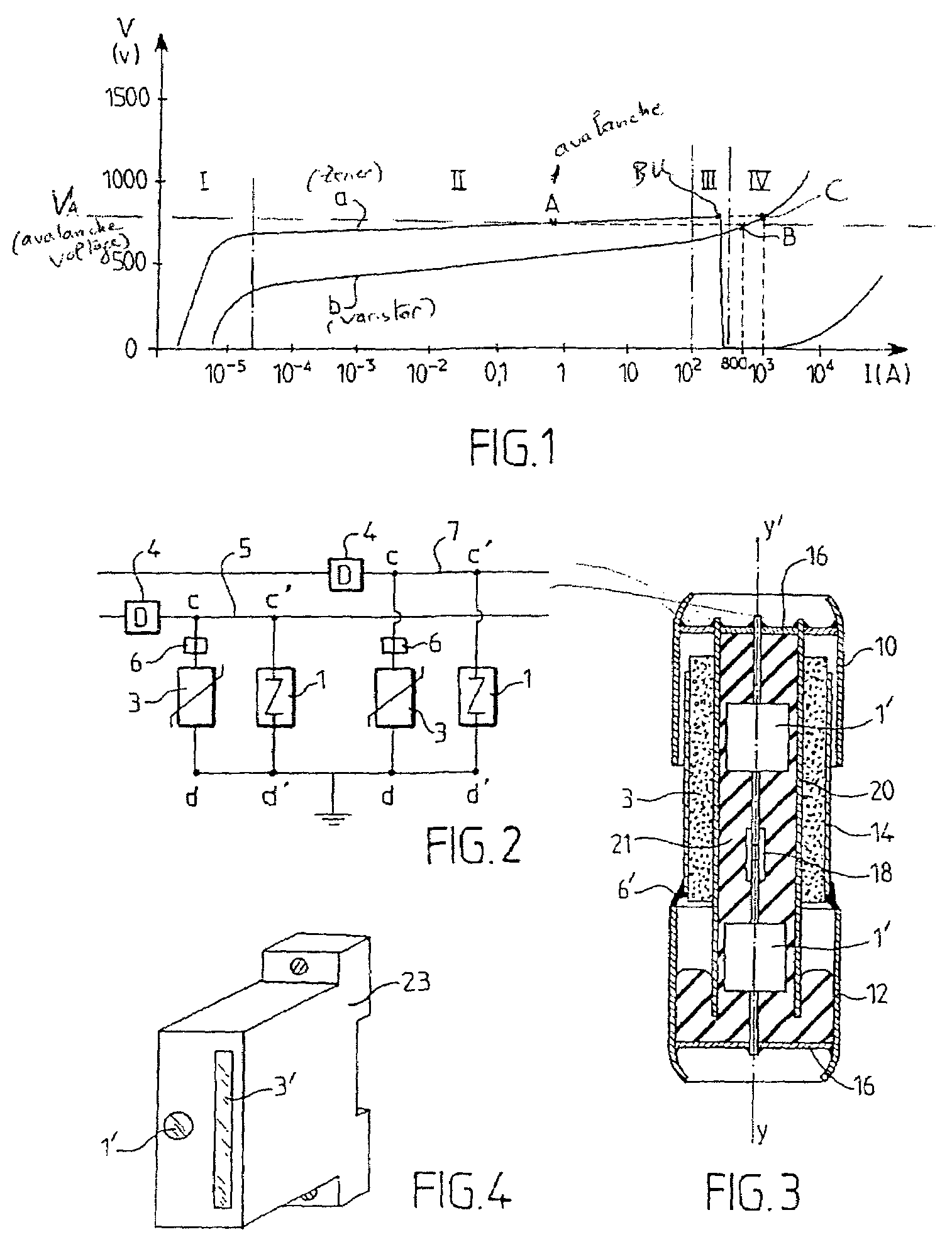
[0032]As shown in FIG. 2, two lightning arrester elements have been associated in parallel, namely a Zener diode lightning arrester element 1 of the type in which a short circuit is established between its terminals when a certain level of voltage surge is attained, and a varistor 3, so that their respective terminals c and c′, on the one hand, and d and d′, on the other hand, are common.

[0033]The lightning arrester is intended to ensure protection of an electric line 5. To that end, one of the common terminals c, c′ of the two lightning arrester elements 1 and 3 is connected to line 5 and their other common terminal d, d′ is connected to earth. A disconnector 4 is disposed on the line 5 upstream of the lightning arrester elements 1 and 3 and another disconnector 6 is disposed just upstream of the varistor 3. The other line 7 of the installation may be protected in the same way.

[0034]FIG. 1 shows the respective characteristics a and b of the two lightning arrester elements 1 and 3, ...


PUM


Abstract

A device for protection against voltage surges in an electric power supply line includes at least two elements (1′, 3), namely a Zener diode lightning arrester (1′) fast-blow in short circuit, and a varistor (3), arranged in parallel. One of the terminals common to the two elements (1′, 3) is connected to the line to be protected, and the other common terminal is connected to earth or to a common conductor element.

Description

BACKGROUND OF THE INVENTION[0001]The present invention relates to a device intended to ensure protection of electrical apparatus against voltage surges which sometimes occur on the conductors used in electric energy distribution networks, particularly in the event of lightning striking.[0002]The prior state of the art has proposed a very diverse quantity of lightning arrester devices which are connected between a wire of the network and earth or a common conductor element, and which comprise components which, in normal functioning, act like neutral elements but which, in the event of violent voltage surge, become conducting so that they divert the current due to the voltage surge and in particular to the lightning, thus protecting the installation disposed downstream against the destructive effects of such voltage surge.[0003]The technical characteristics which are required of such apparatus are very varied, with the result that, up to the present time, no lightning arrester device ...

Claims


Application Information

Patent Timeline
Patent Type & Authority Patents(United States)
IPC IPC(8): H02H1/00H02H9/04
CPCH02H9/042H02H9/044
Inventor GIRARD, FRANCOIS
Owner ADEE ELECTRONICS
Why Eureka
Try Eureka