Peak current sharing in a multi-phase buck converter power system

a power system and multi-phase technology, applied in the direction of automatic control, process and machine control, instruments, etc., can solve the problems of constant on-time controllers, instability and susceptibility to noise, and difficulty in implementing average current sharing, so as to achieve constant on-time control

Active Publication Date: 2006-09-12
ANALOG DEVICES INC
View PDF9 Cites 35 Cited by
  • Summary
  • Abstract
  • Description
  • Claims
  • Application Information

AI Technical Summary

Problems solved by technology

This creates two problems for constant ON-time controllers, stability and susceptibility to noise.
This delay makes average current sharing difficult to implement.
This may not be desirable since during the occurrence of a current imbalance it will take many cycles for the control loop to correct the imbalance.
However, circuit 200 does not have adequate performance because even small errors in the ON-time pulse width may result in very large current sharing errors.
The drawback to this technique is that it is hard to stabilize.
Furthermore, since GMA 333 must have a very low bandwidth, it will take many switching cycles for this system to correct for current sharing errors.

Method used


Image

  • Peak current sharing in a multi-phase buck converter power system
  • Peak current sharing in a multi-phase buck converter power system
  • Peak current sharing in a multi-phase buck converter power system

Examples


Embodiment Construction

[0032]In the following description, numerous specific details are set forth to provide a thorough understanding of the present invention. However, it will be obvious to those skilled in the art that the present invention may be practiced without such specific details. In other instances, well-known circuits may be shown in block diagram form in order not to obscure the present invention in unnecessary detail. For the most part, details concerning timing considerations and the like have been omitted in as much as such details are not necessary to obtain a complete understanding of the present invention and are within the skills of persons of ordinary skill in the relevant art.

[0033]Refer now to the drawings wherein depicted elements are not necessarily shown to scale and wherein like or similar elements are designated by the same reference numeral through the several views.

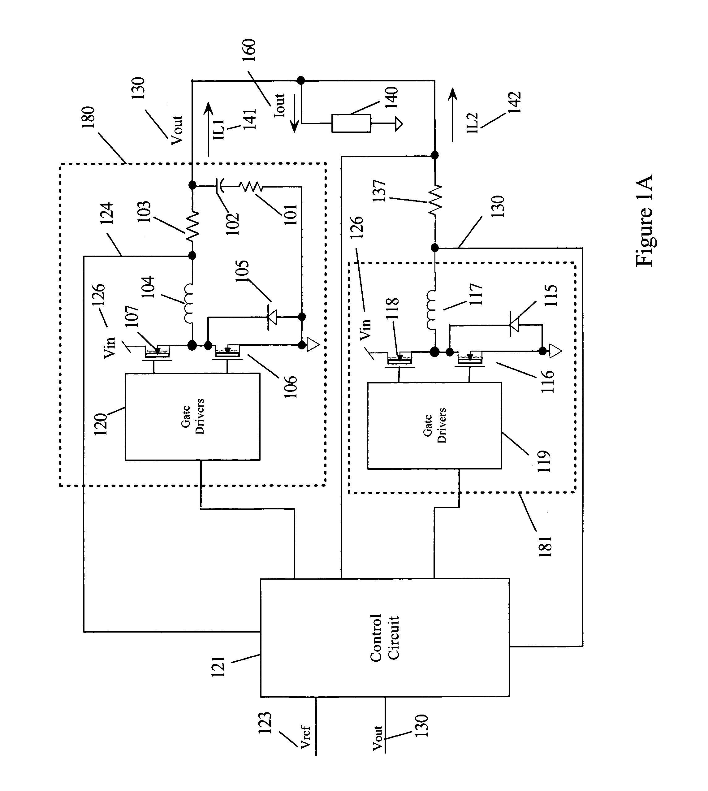
[0034]FIG. 4A is a circuit diagram of a two-phase converter 400 with peak current sharing and constant ON-time c...


PUM


Abstract

A plurality of constant ON-time buck converters are coupled to a common load. The output of each buck converter is coupled to a common load via a series sense resistor. The regulated output voltage across the common load is compared to a reference voltage to generate a start signal. The start signal is alternately coupled to the controller on each buck converter. The ON-time of a master buck converter is terminated when a ramp signal generated from the regulator input voltage exceeds the reference voltage. All other slave converters have an ON-time pulse started by the start signal and stopped by comparing a sense voltage corresponding to their output current during their ON-time pulse to the peak current in the master converter during its ON-time. A counting circuit with an output corresponding to each of the plurality of buck converters is used to select which buck converter receives the start signal.

Description

TECHNICAL FIELD[0001]The present invention relates in general to controllers for switching regulators and in particular to controllers that set a relatively constant ON-time for the switching devices controlling switching regulators that have multi-phase outputs.BACKGROUND INFORMATION[0002]Constant ON-time controllers are used in a class of buck regulators that use the output voltage ripple to initiate an ON-time whenever the regulator output voltage falls below a reference voltage. The ON-time is terminated (generating an ON-time pulse) by circuitry in response to other conditions (e.g., level of regulator input). During the ON-time pulse, energy is supplied directly from the regulator input voltage to the regulator output via an electronic switching device. Likewise, when the ON-time pulse has terminated, stored energy from the regulator input voltage is supplied to the regulator output. Most constant ON-time regulators include circuits that adjust the ON-time pulse duration as a ...

Claims


Application Information

Patent Timeline
Patent Type & Authority Patents(United States)
IPC IPC(8): G06F1/26G05F1/24G05B24/02G06F1/32G06F1/00H02M3/158
CPCH02M3/1584
Inventor PULLEN, STUARTGROOM, TERRY J.
Owner ANALOG DEVICES INC
Why Eureka
Try Eureka