Expandable coupling

a tubular extension and expandable technology, applied in the direction of hose connection, hose connection, manufacturing tools, etc., can solve the problems of differential deformation of the different thread parts of the connection, affecting the integrity of the connection, and affecting the so as to prevent stress concentration and facilitate axial movement of the nose, the effect of reducing the risk of slipping

Inactive Publication Date: 2006-09-19
WEATHERFORD TECH HLDG LLC
View PDF103 Cites 27 Cited by
  • Summary
  • Abstract
  • Description
  • Claims
  • Application Information

AI Technical Summary

Benefits of technology

[0028]Preferably, the first tubular has a leading end portion or nose adapted to be radially constrained by the second tubular. For example, the second tubular may define an undercut slot, recess or groove in which the nose is received. This prevents the nose from separating from the second tubular, and in particular from encroaching into the internal diameter of the coupling following expansion, as might otherwise occur due to end effects, where the free end or nose tends to radially contract more than adjacent portions of the tubular. Alternatively, or in addition, the groove may extend axially and be dimensioned to accommodate axial extension of the first tubular relative to the second tubular. The groove may accommodate a deformable sealing material, such as an elastomer, in particular an elastomeric o-ring or the like which will be energised by relative axial extension of the male thread. In one embodiment, the free end of the first tubular member is not threaded, to facilitate axial movement of the nose relative to the second tubular, and thus to energise, or further energise, the deformable seal, where provided. Preferably, the groove features a rounded recess angle, to prevent stress concentration and to alleviate stress-induced cracking upon extension.
[0029]Preferably, the first tubular comprises at least one sealing member for sealing engagement with an opposing surface of the second tubular, most preferably for sealing engagement with an opposing surface adjacent a free end of the second tubular. Conveniently, the sealing engagement is provided with a surface spaced sufficiently from the free end of the unexpanded second tubular to accommodate axial shrinkage of the tubular following expansion. The end effect of the expanded free end also serves to energise the sealing member. Most preferably, the sealing member is in the form of an elastomer. At least two axially spaced elastomers may be provided. The sealing members may be located in appropriate grooves in the first tubular.

Problems solved by technology

However, where strings of tubulars are to be expanded to describe a larger diameter, it has been found that the integrity of the coupling may be compromised.
The applicant has found that in a conventional thread this differential expansion tends to produce an adverse effect on the thread integrity.
Integrity problems may also occur in couplings which are expanded using alternative expansion methods such as solid cone expansion or hydraulic expansion techniques, which may also cause differential deformation in the different thread parts of the connection.
However, when the expansion cone is passed through a conventional threaded connection, the male and female, or pin and box thread portions are caused to axially contract at different rates, thus causing adverse deformation due to the interference between the different thread portions.
It is this adverse deformation which diminishes the mechanical and hydraulic integrity of the connection.
Specifically, applicant has observed that during solid cone expansion of a conventional connection, the box is initially caused to move or pull away axially with respect to the pin causing interference between adjacent threads resulting in deformation of inter-engaging thread portions, with further expansion causing differential axial shrinkage in both the pin and box, the overall result being an adverse interference in the connection.

Method used


Image

  • Expandable coupling
  • Expandable coupling
  • Expandable coupling

Examples


Embodiment Construction

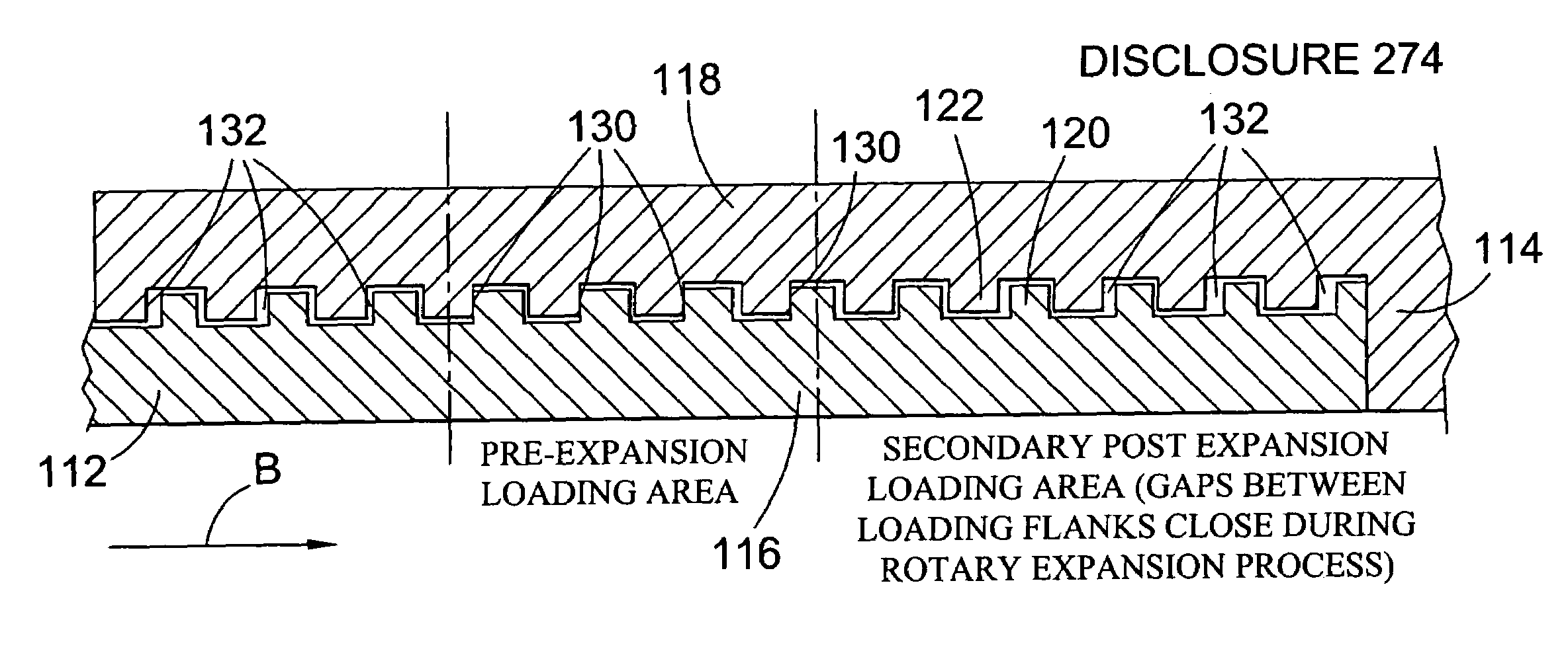
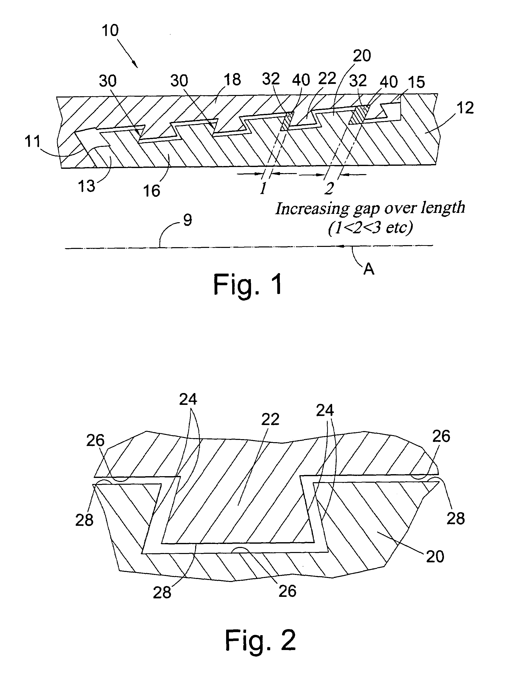
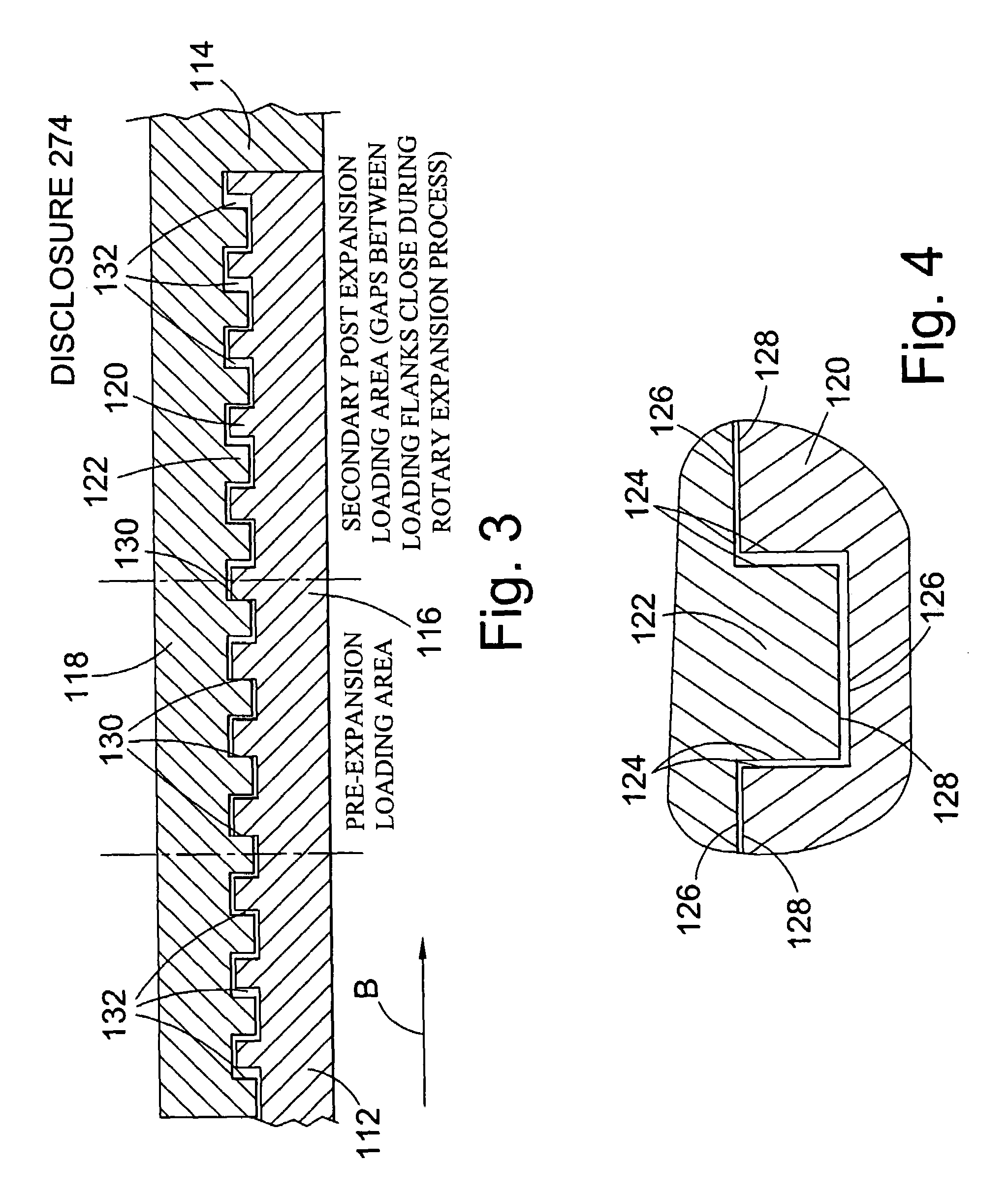
[0044]Reference is first made to FIG. 1 of the drawings in which there is shown a sectional view of a portion of a tubular threaded coupling 10 connecting the ends of first and second downhole tubulars 12, 14. The end of the first tubular 12 features a male threaded portion 16, or a pin connection, while the adjacent end of the second tubular 14 features a corresponding female threaded portion 18, or box connection. The threaded portions 16, 18 in this embodiment are tapered with respect to the longitudinal axis 9 of the coupled tubulars 12, 14. The threaded portions 16, 18 each comprise a plurality of inter-engaging teeth 20, 22, and as more clearly shown in FIG. 2, the teeth 20, 22 of the threaded portions define flanks 24, roots 26 and crests 28.

[0045]In the embodiment shown in FIGS. 1 and 2 the thread teeth 20, 22 have a dovetail profile, that is, the flanks 24 of each tooth 20, 22 are inclined at an angle, that is non-perpendicular, relative to the adjacent roots 26 and crests ...


PUM

PropertyMeasurementUnit
hydraulic pressureaaaaaaaaaa
widthaaaaaaaaaa
lengthaaaaaaaaaa

Abstract

An expandable tubular coupling (10) includes first and second thread portions (12,14) each comprising a plurality of inter-engaging teeth (20,22), wherein at least one tooth on the first thread portion (12) engages a corresponding tooth on the second thread portion (14) and the remainder of said inter-engaging teeth (20,22) define respective gaps (32) therebetween.

Description

BACKGROUND OF THE INVENTION[0001]1. Field of the Invention[0002]The present invention relates to coupling tubulars, and in particular to coupling expandable tubulars, most particularly expandable downhole tubulars.[0003]2. Description of the Related Art[0004]Downhole tubulars, such as bore-lining casing and liners, are typically coupled together by means of threaded connectors, or by providing adjacent ends of tubulars with male and female, or pin and box, threaded ends. For conventional applications, such coupling arrangements are generally satisfactory, providing secure, pressure tight connections. However, where strings of tubulars are to be expanded to describe a larger diameter, it has been found that the integrity of the coupling may be compromised.[0005]This is particularly the case where expansion is achieved using a rotary expansion tool. Such a tool expands the male or pin thread portion by cold working, reducing the wall thickness of the portion resulting in a correspondi...

Claims


Application Information

Patent Timeline
Patent Type & Authority Patents(United States)
IPC IPC(8): B21D39/00E21B17/042E21B43/10F16L13/14F16L13/16
CPCE21B17/042E21B43/103E21B43/106F16L13/168F16L13/147Y10T29/4994Y10T29/49911Y10T29/49881F16L13/14
Inventor ELLINGTON, PETERMACAULAY, IAIN CAMERON
Owner WEATHERFORD TECH HLDG LLC
Why Eureka
Try Eureka