Winder apparatus with transfer brush roll

a technology of winder and web, which is applied in the direction of transportation and packaging, thin material processing, filament handling, etc., can solve the problems of waste of product, mis-transfer of one of the webs of material, undesirable down time of equipment, etc., and achieve high-consistency and reliable web-transfer

Active Publication Date: 2006-09-19
HUDSON-SHARP MACHINE COMPANY
View PDF10 Cites 3 Cited by
  • Summary
  • Abstract
  • Description
  • Claims
  • Application Information

AI Technical Summary

Benefits of technology

[0008]The present invention is directed to a winder apparatus for winding webs of materials into coreless rolls, with the apparatus including an improved arrangement for effecting transfer of the webs onto associated winding spindles for initiating winding thereon. The apparatus includes a rotatably driven transfer brush assembly positioned in operative association with an apparatus conveyor and the winding spindles, with the brush assembly configured to engage the leading edge portion of one of the webs, and thereby deflect and transfer the web from the conveyor onto the associated winding spindle to initiate winding. The arrangement is desirably straight forward in construction for economical manufacture and use, with highly consistent and reliable web-transfer achieved.
[0012]The brush wheel is engageable with one of the webs for transferring that one of the webs onto one of the spindles when it is in the transfer position. By this action, winding of the web onto the spindle is initiated, with the spindle being rotatably driven at a speed coordinated with the speed at which the webs are being conveyed. In the preferred embodiment, each of the winding spindles includes air passageways, with application of vacuum through these passageways facilitating initiation of winding, and the direction of air pressure outwardly through the passageways facilitating discharge of a completed roll from the spindle after the turret is indexed to present the roll at a discharge position.
[0014]In the preferred form, the apparatus includes a support roll positioned beneath the conveyor for cooperation with the transfer brush assembly, thereby facilitating transfer of each of the webs from the conveyor onto the associated winding spindle.

Problems solved by technology

Heretofore, operation of such a winder apparatus can inadvertently result in mis-transfer of one of the webs of material, that is, failure to initiate the intended winding of the web onto the winding spindle at the transfer position.
Naturally, such mis-transfers undesirably results in wasted product and undesirable down time for the equipment.
As noted, this existing transfer arrangement can sometimes undesirably result in mis-transfer of the webs of material.
Additionally, this particular component of the winding apparatus is a relatively expensive part to fabricate, entailing substantial machine work for its manufacture.

Method used


Image

  • Winder apparatus with transfer brush roll
  • Winder apparatus with transfer brush roll
  • Winder apparatus with transfer brush roll

Examples


Embodiment Construction

[0019]While the present invention is susceptible of embodiment in various forms, there is shown in the drawings, and will hereinafter be described, a presently preferred embodiment, with the understanding that the present disclosure is to be considered as an exemplification of the invention, and is not intended to limit the invention to the specific embodiment illustrated.

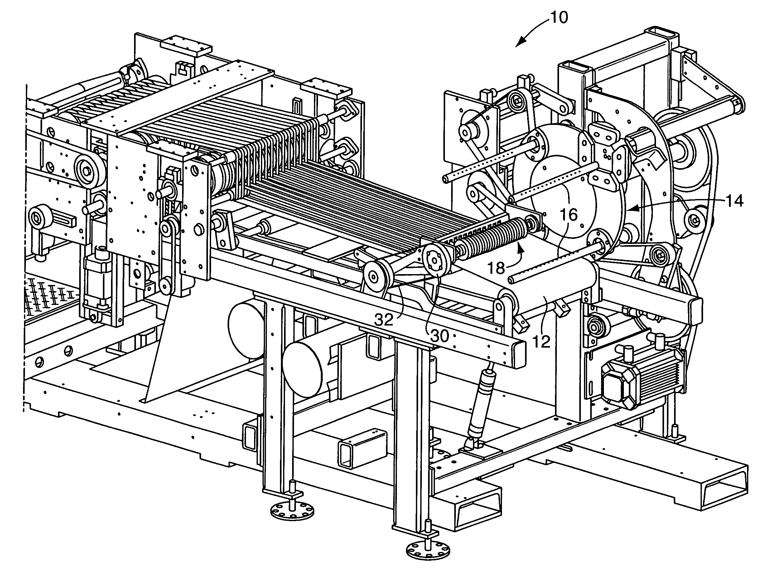
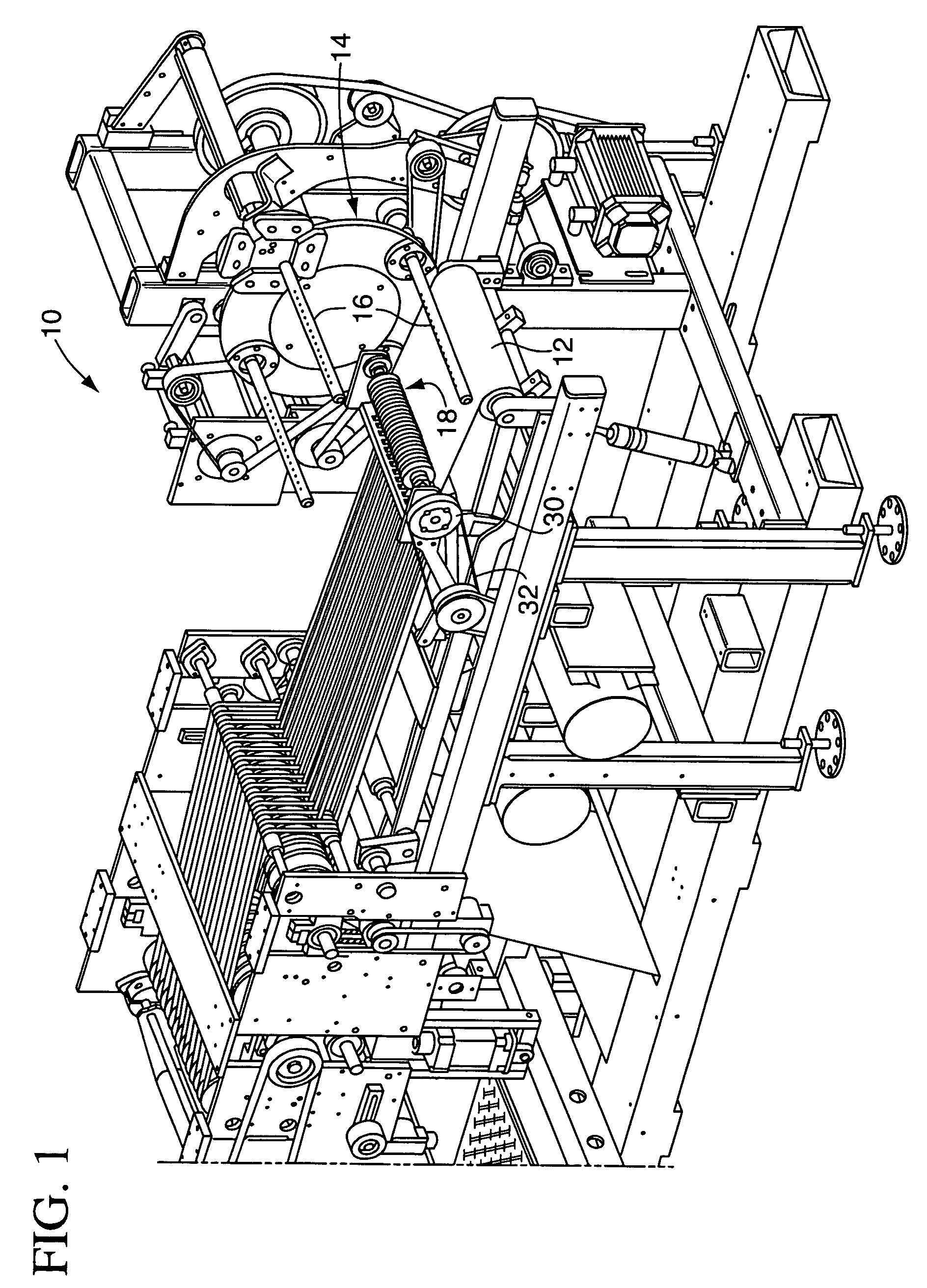
[0020]With reference first to FIG. 1, therein is illustrated a winder apparatus 10 embodying the principals of the present invention. As will be recognized by those familiar with the art, winder apparatus 10 is configured to wind webs of material, typically plastic film bags arranged in an interleaved relationship or end-to-end arrays, into individual, coreless rolls. After winding into individual rolls, the rolls are discharged from the apparatus for subsequent handling.

[0021]Winder apparatus 10 includes a frame on which a conveyor 12 is mounted for serially conveying the webs of material therealong. The apparatus...


PUM

PropertyMeasurementUnit
widthaaaaaaaaaa
widthaaaaaaaaaa
diameteraaaaaaaaaa

Abstract

A winder apparatus for winding webs of material into rolls includes a conveyor, and a winding turret with a plurality of rotatably driven winding spindles thereon. The winding turret indexes the winding spindles relative to the apparatus conveyor, with each spindle moved to a transfer position wherein a web of material is transferred from the conveyor onto the spindle to initiate roll formation. A rotatably driven transfer brush assembly is positionable in operative association with the conveyor and the spindle in the winding position to facilitate efficient and consistent transfer of a web from the conveyor onto the spindle for roll formation.

Description

TECHNICAL FIELD[0001]The present invention relates generally to an apparatus for winding webs of material into individual rolls, and more particularly to a winder apparatus having a brush roll assembly which facilitates efficient transfer of serially conveyed webs of material onto associated winding spindles of the apparatus.BACKGROUND OF THE INVENTION[0002]Automated winding machines facilitate efficient, high-speed winding of webs of materials, such as interleaved or connected plastic film bags, into individual rolls. An apparatus of this nature includes a conveyor along which the webs of material are serially conveyed, and an associated, indexable winding turret having a plurality of winding spindles mounted thereon. The spindles of the winding turret can each be indexed to a so-called transfer position, with winding of a roll initiated by transferring a leading edge portion of one of the material webs onto the winding spindle. The spindle is rotatably driven in coordination with ...

Claims


Application Information

Patent Timeline
Patent Type & Authority Patents(United States)
IPC IPC(8): B65H19/30B65H18/22B65H19/22B65H19/28
CPCB65H18/22B65H19/22B65H19/2207B65H19/28B65H2408/23157B65H2301/414222B65H2301/41468
Inventor FIEDLER, LEE
Owner HUDSON-SHARP MACHINE COMPANY
Why Eureka
Try Eureka