Subsurface drainage system and drain structure therefor

a drainage system and subsurface technology, applied in the direction of applications, ground pavings, roads, etc., can solve the problems of inconvenient installation, inconvenient transportation of such drain structures, and inability to use the field,

Active Publication Date: 2006-09-19
AIRFIELD SYST
View PDF15 Cites 37 Cited by
  • Summary
  • Abstract
  • Description
  • Claims
  • Application Information

AI Technical Summary

Problems solved by technology

Further, well drained playing fields eliminate or significantly decrease the time during which heavy precipitation would make the field unuseable.
While use of the drainage structure described above has met with success, the transportation of such drain structures can be expensive, and its installation tedious and time consuming.
It has been suggested to form openings in the sidewall that would promote drainage from the cylindrical support member, but the formation of such openings result in the creation of sharp edges that may cut or puncture the impermeable liner during the installation process or after the drain structure is covered with the turf and the soil that makes up the root zone layer.

Method used


Image

  • Subsurface drainage system and drain structure therefor
  • Subsurface drainage system and drain structure therefor
  • Subsurface drainage system and drain structure therefor

Examples


Embodiment Construction

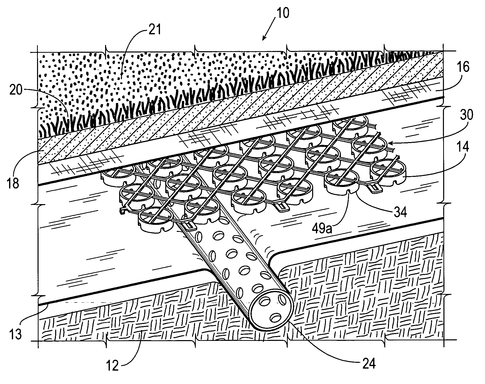
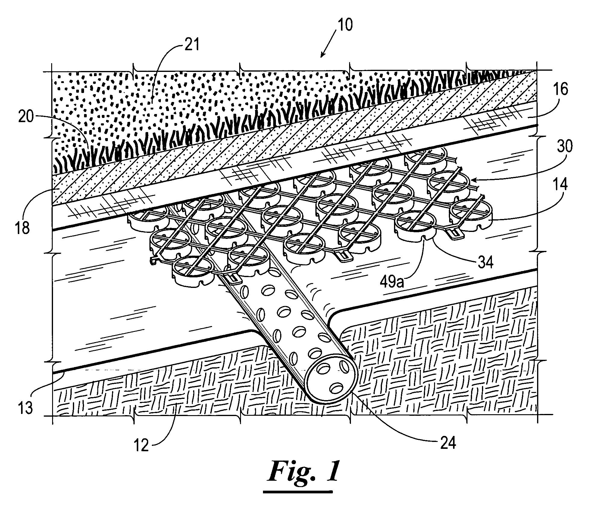
[0017]Referring now to the drawings, and more particularly to FIG. 1, shown is a subsurface drainage system 10 constructed in accordance with the present invention. The subsurface drainage system 10 includes a base layer 12, an impermeable liner 13, a drain structure 14, a semi-permeable filter fabric layer 16, a root zone layer 18, and a turf layer 20 defining a playing surface 21. In instances where it is desirable to allow some permanent deep infiltration of surface drainage, the impermeable liner 22 may be replaced with a semi-permeable geotextile fabric.

[0018]The subbase 12 typically includes a subsoil that has been graded and packed to predetermined slope (e.g., five percent) to direct by gravity the movement of subsurface water. The subbase 12 is sloped preferably from about one degree to about fifteen degrees to induce downhill water flow. A perforated collector pipe 24 preferably is installed at the down slope terminus of each sloped portion of the subbase 12. The subbase 1...


PUM


Abstract

A subsurface drainage assembly for directing fluid drainage from a surface including a plurality of drain structure panels linked together in a manner that permits movement of one drain structure panel relative to the adjacent drain structure panel. The drain structure panels have a laterally extensive backing grid and a plurality of spaced apart support members projecting therefrom. The support members have at least one fluid flow opening formed through a sidewall so as to intersect a lower end of the support members at two rounded corners. The support members are spaced so that the support members are nestable between the support members of an identical drain structure panel when the drain structure panels are arranged in an inverted relationship with respect to one another. The drain structure panel may be placed on an impermeable liner having an upper surface with a plurality of ridges defining troughs therebetween.

Description

BACKGROUND OF THE INVENTION[0001]1. Field of the Invention[0002]The present invention generally relates to systems for subsurface fluid drainage and storage, and more particularly, but not by way of limitation, to a subsurface drainage system and a drain structure therefor which promotes rapid infiltration of water through a subsoil structure.[0003]2. Brief Description of Related Art[0004]It is known that adequate drainage is a key to maintaining quality turf on athletic playing fields, such as football and soccer fields, baseball diamonds, golf courses, and the like. Further, well drained playing fields eliminate or significantly decrease the time during which heavy precipitation would make the field unuseable.[0005]Previous efforts have been made in the field of subsurface drainage systems for sports fields and the like. In particular, U.S. Pat. No. 5,848,856 has been issued to William Bohnhoff. The Bohnhoff '856 patent discloses a subsurface drainage system that includes a base l...

Claims


Application Information

Patent Timeline
Patent Type & Authority Patents(United States)
IPC IPC(8): E02B11/00E01C3/00
CPCE01C13/083Y10T403/10
Inventor BLACKWOOD, CHARLES R.
Owner AIRFIELD SYST
Why Eureka
Try Eureka