Hardline coaxial cable connector

a coaxial cable and connector technology, applied in the direction of coupling devices, two-part coupling devices, electrical apparatus, etc., can solve the problems of disadvantageous increasing the number of components in the connector, disadvantageous altering the characteristic impedance of the connector-coaxial cable combination, and disadvantageous relative motion of the cabl

Inactive Publication Date: 2006-09-19
CORNING OPTICAL COMM LLC
View PDF13 Cites 75 Cited by
  • Summary
  • Abstract
  • Description
  • Claims
  • Application Information

AI Technical Summary

Benefits of technology

[0011]Another object of the present invention is to provide a connector that can at least partially undeform the deformed terminating end of the outer conductor of the coaxial cable as the coaxial cable is inserted into the connector.
[0012]Yet another object of the present invention is to provide a connector that has a sleeve that does not adversely affect the characteristic impedance of the connector-coaxial cable combination.
[0014]Yet a further object of the present invention is to provide a connector that is easier to compress.

Problems solved by technology

However, the metallic nature of such sleeves disadvantageously alters the characteristic impedance of the connector-coaxial cable combination from its nominal seventy-five (75) ohms.
Because the sleeve and the insulator of known F-type connectors are made of different materials, the sleeve and the insulator must be separate components, thus disadvantageously increasing the number of components in the connector.
With such compression style connectors, the cable may disadvantageously have some relative motion with respect to the connector when the jacket gripping part attempts to seize the outer insulation of the coaxial cable.
Known prior art compression style connectors that seize two or more portions of the coaxial cable simultaneously are disadvantageously difficult to compress.

Method used


Image

  • Hardline coaxial cable connector
  • Hardline coaxial cable connector
  • Hardline coaxial cable connector

Examples


Embodiment Construction

[0040]It should be understood that the embodiments discussed below are only examples of the many advantageous uses of the innovative teachings herein. In general, statements made in the specification of the present application do not necessarily limit any of the various claimed inventions. Some statements may apply to some inventive features but not to others. In general, unless otherwise indicated, singular elements may be in the plural and vice versa with no loss of generality. The terms first, second, third, and the like, in the description and in the claims, if any, are used for distinguishing between similar elements and not necessarily for describing a sequential or chronological order. The terms top, front, side, and the like, in the description and in the claims, if any, are used for descriptive purposes and not necessarily for describing relative positions.

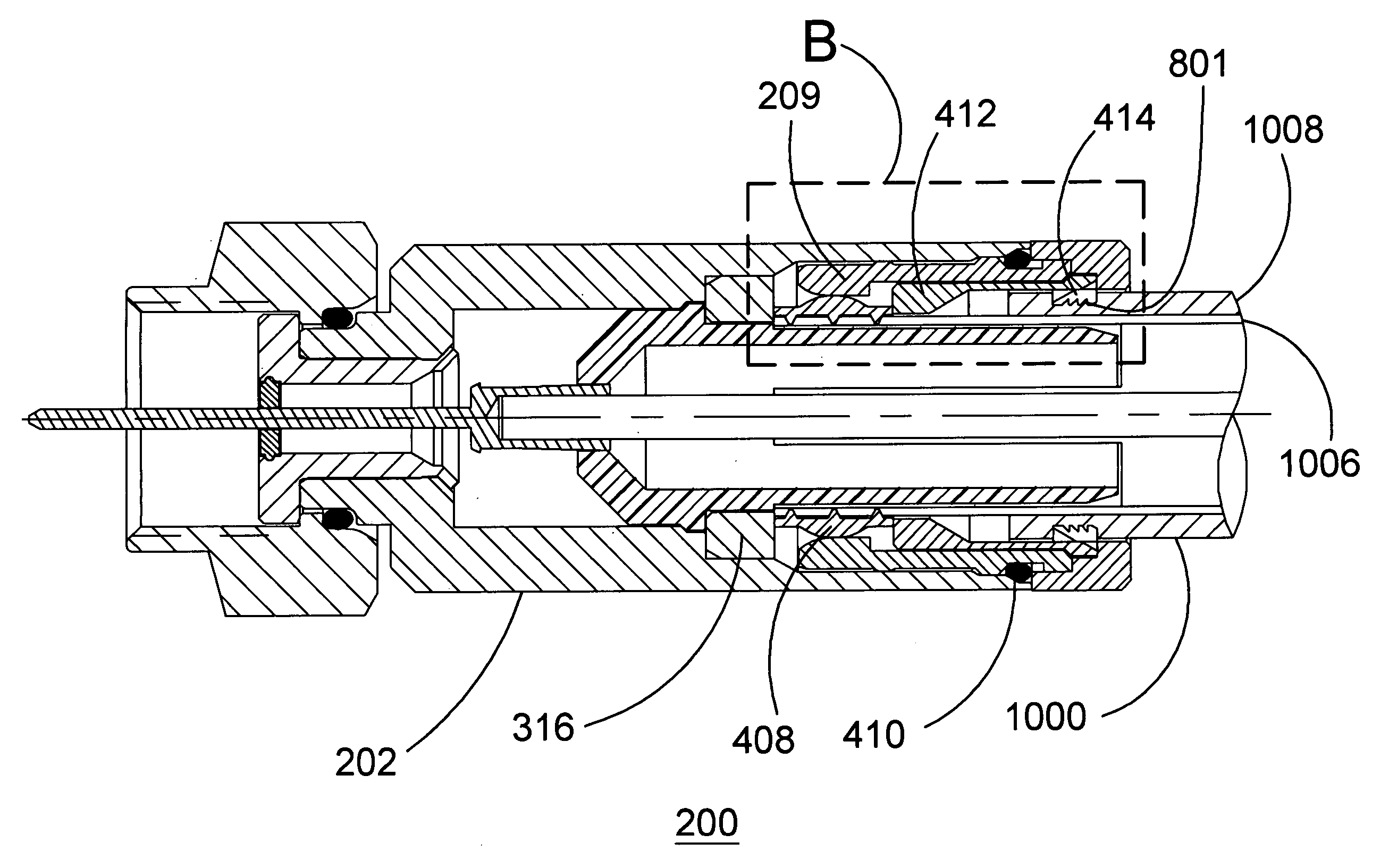
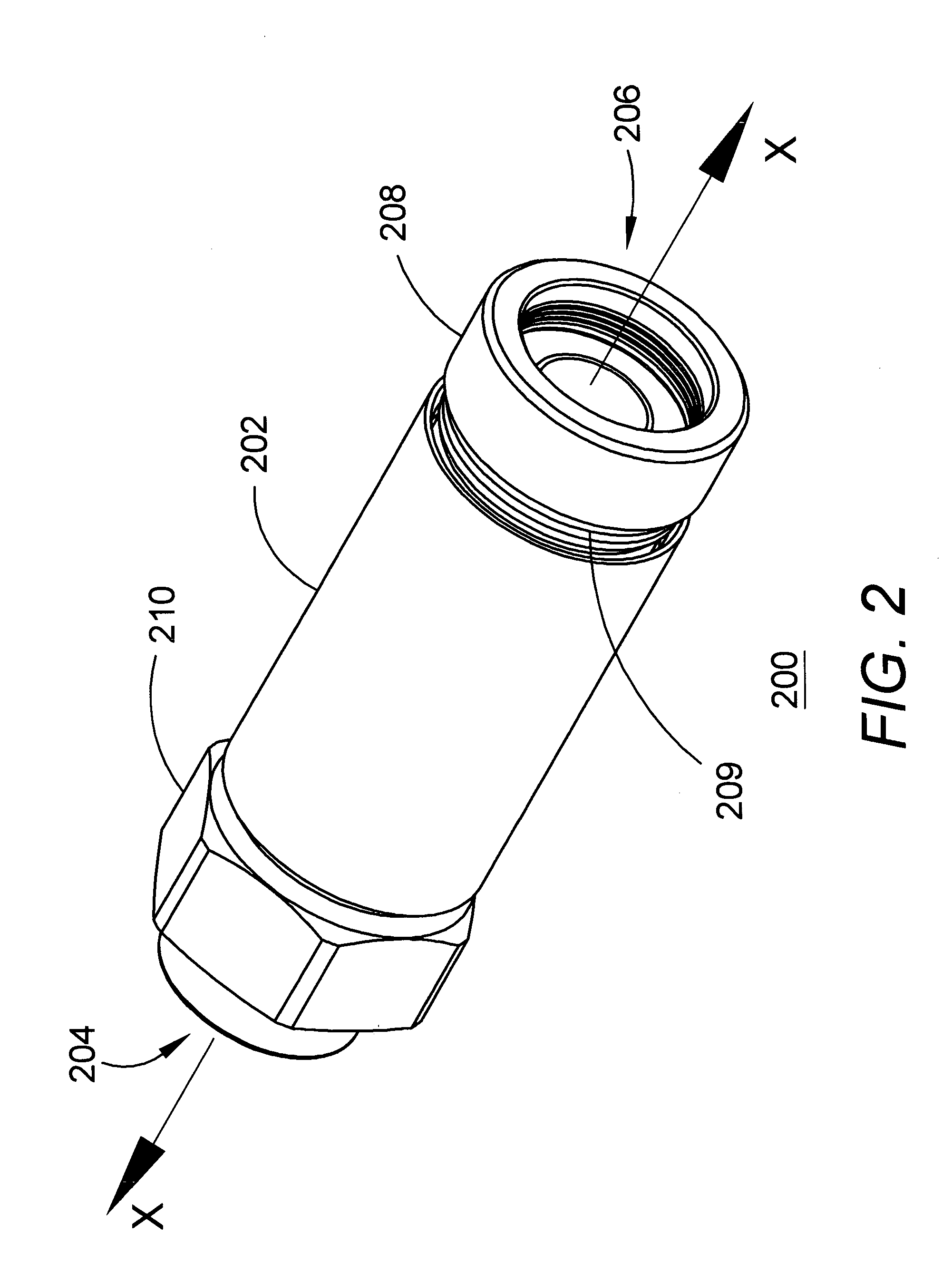
[0041]FIG. 2 illustrates a perspective view of a male, F-type, compression style connector, constructed in accordance w...


PUM


Abstract

An axially-compressible connector (200) for a hardline coaxial cable (1000) has a housing that includes a body (202), a coupling nut (210) and a compression can (208). A nonmetallic sleeve (302), which is mounted within the housing, has a tubular portion and an integral insulator portion. The insulator portion holds a contact (306) that has arms (311–314) for seizing an inner conductor (1002) of the hardline coaxial cable. A ferrule (408) is slip fit mounted within the housing, and seizes an outer conductor (1006) of the hardline coaxial cable. A gripping member (414) is mounted within the housing and seizes a jacket (1008) of the hardline coaxial cable. An actuator (412), which is mounted within the housing around a portion of the tubular portion of the sleeve, has an angled surface (413) to guide an end of the outer conductor toward the tubular portion of the sleeve, as the tubular portion of the sleeve is inserted into the end of the coaxial cable. The jacket is gripped by the gripping member only after the outer conductor is seized by the ferrule.

Description

BACKGROUND OF THE INVENTION[0001]1. Field of the Invention[0002]The present invention relates generally to electrical connectors, and more specifically to an axially-compressible electrical connector for use with a hardline coaxial cable.[0003]2. Description of the Related Art[0004]A hardline coaxial cable is a coaxial cable that has a solid, as opposed to a braided, outer conductor, which may be surrounded by an outer insulative jacket. One such hardline coaxial cable is the QUANTUM REACH® coaxial cable, catalog number QR320, which has a solid aluminum outer conductor and a solid copper clad aluminum inner conductor, and which is manufactured by CommScope Inc., of Hickory, N.C. A popular style of coaxial cable connector is a male, F-type axially-compressible connector. Prior to attaching such a hardline coaxial cable to such a connector, a coaxial cable coring tool is used to remove a predetermined amount of the dielectric material between the inner and outer conductors at a termin...

Claims


Application Information

Patent Timeline
Patent Type & Authority Patents(United States)
IPC IPC(8): H01R9/05H01R13/646
CPCH01R9/0524H01R24/40H01R2103/00
Inventor KISLING, BRIAN L.MILLER, THOMAS D.
Owner CORNING OPTICAL COMM LLC
Why Eureka
Try Eureka