Image processor capable of edge enhancement in saturated region

a technology of image processing and saturated region, applied in the field of image processing, can solve the problem that image processing effect such as edge enhancement cannot be achieved in pixel, and achieve the effect of effective image processing and simple construction

Inactive Publication Date: 2006-09-19
SOCIONEXT INC
View PDF23 Cites 0 Cited by
  • Summary
  • Abstract
  • Description
  • Claims
  • Application Information

AI Technical Summary

Benefits of technology

[0010]Accordingly, it is an object of the present invention to provide a image processor capable of effectively performing an image processing such as an edge enhancement processing even in a region of saturated pixel values, with a simple construction.

Problems solved by technology

In the prior art, when an edge enhancement processing is applied on image data, an image processing effect such as edge enhancement could not be achieved in pixel value

Method used


Image

  • Image processor capable of edge enhancement in saturated region
  • Image processor capable of edge enhancement in saturated region
  • Image processor capable of edge enhancement in saturated region

Examples


first embodiment

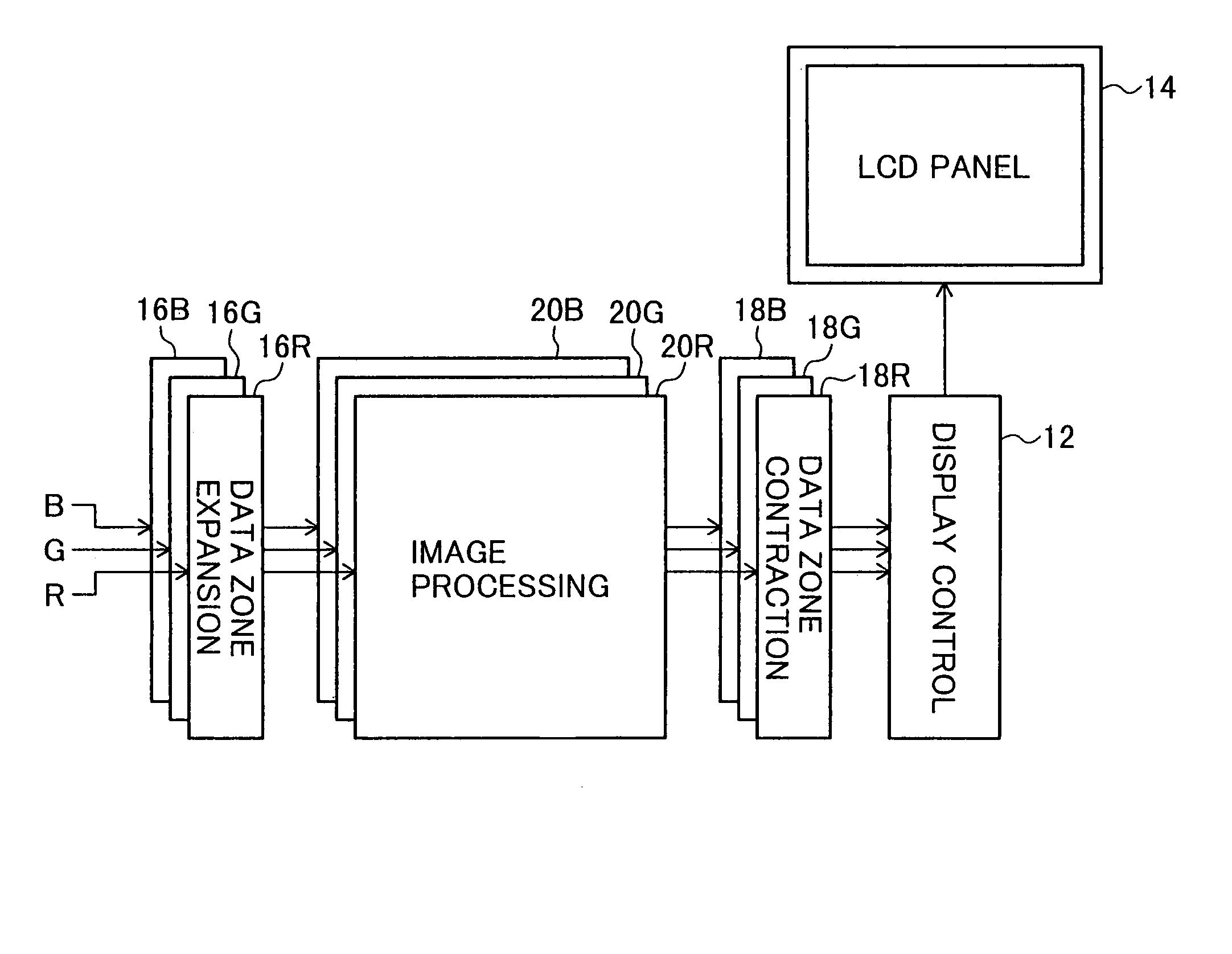
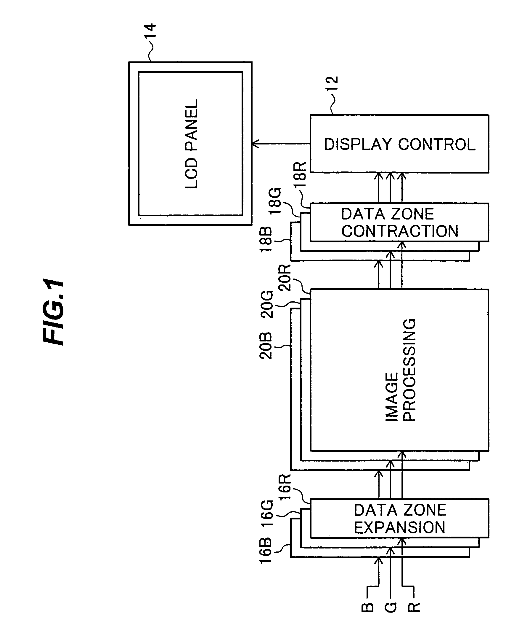
[0026]FIG. 1 is a schematic block diagram showing an image display device of a first embodiment according to the present invention.

[0027]Digital image signals in three primary colors R, G and B are provided to data zone expansion circuits 16R, 16G and 16B, respectively.

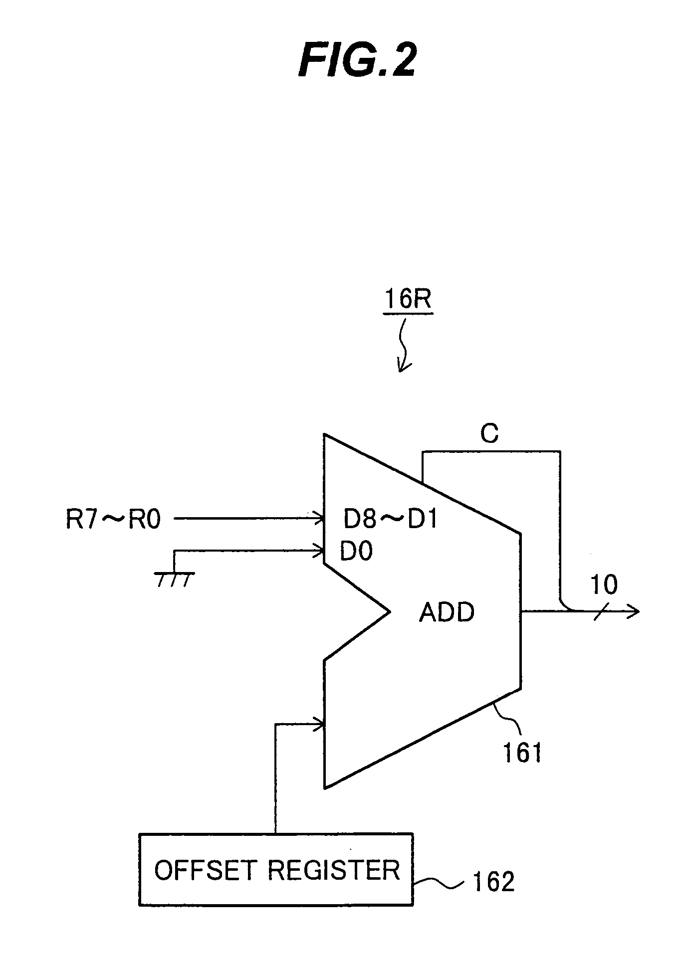
[0028]The data zone expansion circuit 16R linearly converts an input signal R in a range of 0 to MAXO to an output signal (αX R+β), in a range of 0 to MAX1 in order to

[0029]accommodate the output signal with sufficient upper and lower margins. Herein, MAX1>MAXO, and α and β are constants satisfying conditions of α>1 and , β≧0. For simplification of a circuit, generally, α=2n, n is a positive integer and a is 0 or a positive integer.

[0030]For example, the input signal R is a signal as shown in FIG. 9 having a pixel position on a display line as a time axis, and is converted to a signal shown in FIG. 4.

[0031]The minimum value 0 and the maximum value MAXO of the input signal R are converted to β and αX MAXO+β, respective...

second embodiment

[0049]FIG. 7(A) shows a data zone expansion circuit 16RA employed in an image processor of a second embodiment according to the present invention.

[0050]The circuit 16RA includes a 9 bit up-counter. The output of the data zone expansion circuit 16RA has a parallel output obtained by providing one pulse of a clock to the clock input CK after a parallel input R7 to RO is loaded on the counter, and an added lowest bit “0”. The output is 2(R+1)=2R+2 for the input R. That is, α=2 and β=2.

[0051]FIG. 7(B) shows a data zone contraction circuit 18RA employed in the image processor of the second embodiment according to the present invention.

[0052]The data zone contraction circuit 18RA includes a 10 bit down-counter. A parallel input RI9 to RIO is loaded on the counter, 2 pulses of the clock 0 are provided to the clock input CK thereof, and the output of the data zone contraction circuit 18R is obtained from an intermediate 8 bit parallel output D08 to D01 excluding LSB and MSB among 10 bits. T...


PUM


Abstract

An image processing device includes a data zone expansion circuit and an image processing circuit. The data zone expansion circuit receives input data, increases a number of data bits of the input data, and provides data with the increased number of data bits. The image processing circuit performs image processing on the data with the increased number of data bits.

Description

CROSS-REFERENCE TO RELATED APPLICATIONS[0001]This application is a continuation of application Ser. No. 09 / 737,502, filed Dec. 18, 2000 U.S. Pat. No. 6,795,087.[0002]This application is based upon and claims the priority of Japanese application no. 2000-041393, filed Feb. 15, 2000, and U.S. patent application Ser. No. 09 / 737,502, filed Dec. 18, 2000, the contents being incorporated herein by reference.BACKGROUND OF THE INVENTION[0003]1. Field of the Invention[0004]The present invention relates to an image processor incorporated in a display device such as a flat panel display device or a CRT display device, or connected to a display device.[0005]2. Description of the Related Art[0006]It has been required to improve image quality by processing digital image signals, in company with increase, in processing speed of an LSI.[0007]FIG. 8 is a schematic block diagram showing a prior art image display device.[0008]Digital image signals of three primary colors R, G and B are provided to res...

Claims


Application Information

Patent Timeline
Patent Type & Authority Patents(United States)
IPC IPC(8): G09G5/00H04N5/208G06T5/00G06T5/20G09G5/36H04N5/262
CPCG06T5/003G06T2207/20192G06T2207/10024
Inventor GENBA, AKIRA
Owner SOCIONEXT INC
Why Eureka
Try Eureka