Radiation imaging system, control method for the same, and program

a technology of radiation imaging and control method, applied in the field of radiation imaging system, can solve the problems of inconsistency between the x-ray sensor unit and the main control unit, increase the cost of x-ray sensor unit, so as to prevent the delay in display of radiation image or delay in radiation control. effect of image processing

Inactive Publication Date: 2011-02-03
CANON KK
View PDF26 Cites 3 Cited by
  • Summary
  • Abstract
  • Description
  • Claims
  • Application Information

AI Technical Summary

Benefits of technology

[0028]The present invention has been made in consideration of the above situation, and has as its object to allow a main control unit to efficiently perform image processing such as gradation conversion while preventing delay in display of a radiation image or delay in radiation control.

Problems solved by technology

If the configuration of the X-ray sensor unit is such that the above described correction processing of the sensor characteristics and the image processing, such as sharpening, granularity reduction, and gradation conversion are performed internally, it will increase a cost, heat generation, and size of the X-ray sensor unit.
On the other hand, if the configuration of the X-ray imaging system is such that the X-ray sensor unit outputs a captured X-ray image to the main control unit without processing it, and the main control unit performs the correction processing of the sensor characteristics and all the image processing, the cost, heat generation, and size of the X-ray sensor unit will not be increased.
However, in this case, since the main control unit needs to perform the correction processing of the sensor characteristics, the main control unit needs to comprehend all of the image reception characteristics unique to the sensor, and a problem of inconsistency between the X-ray sensor unit and the main control unit may occur.
This causes increase in communication traffic volume.
Since the X-ray sensor unit and the main control unit are often located some distance apart, the increase in the communication traffic volume will be a major problem.
On the other hand, if the correction processing of the sensor characteristics is performed by the X-ray sensor unit, transmission of the data which is used in correcting the image to the main control unit will be unnecessary.
In this case, since the image data is transmitted to the main control unit after the correction processing of the sensor characteristics is performed on the stored image data, delay may cause in the transmission of the image data to the main control unit.
Thus, the time necessary in transferring the image data from the X-ray sensor unit to the main control unit may be a bottleneck, and delay time that occurs in the display of the image may be considered as a major inconvenience to the user.
Thus, it is necessary to transfer large quantities of data.
Thus, if display of the image is considerably delayed, a difference between the operation and visual recognition will increase and will cause additional inconveniences.
On the other hand, in increasing the data transfer speed, costs of components used in an input / output (I / O) unit will be increased and, further, securing a transmission quality will be difficult.
However, according to this method, the parameter obtained from an analysis result such as the pixel mean value cannot be reflected to the image processing in the frame at that time.
Thus, it is difficult to accurately process the image according to the analysis result.
Thus, the time necessary in the image data transfer becomes a bottleneck, and the delay in the X-ray control may be increased or the reflection of the X-ray control parameter may be delayed a few frames.

Method used


Image

  • Radiation imaging system, control method for the same, and program
  • Radiation imaging system, control method for the same, and program
  • Radiation imaging system, control method for the same, and program

Examples


Embodiment Construction

[0042]Various exemplary embodiments, features, and aspects of the invention will be described in detail below with reference to the drawings.

[0043]In the exemplary embodiments of the present invention described below, an X-ray imaging system using X-ray, which is one type of radiation rays, is used as an example of a radiation imaging system according to the present invention. The radiation imaging system of the present invention, however, is not limited to the X-ray imaging system and, for example, a radiation imaging system using a different radiation ray such as alpha ray, beta ray, or gamma ray may also be used. Further, although the X-ray imaging system is used as the radiation imaging system in the exemplary embodiment of the present invention described below, for example, a radiation imaging apparatus of an X-ray imaging apparatus may also be used.

[0044]A first exemplary embodiment of the present invention will be described.

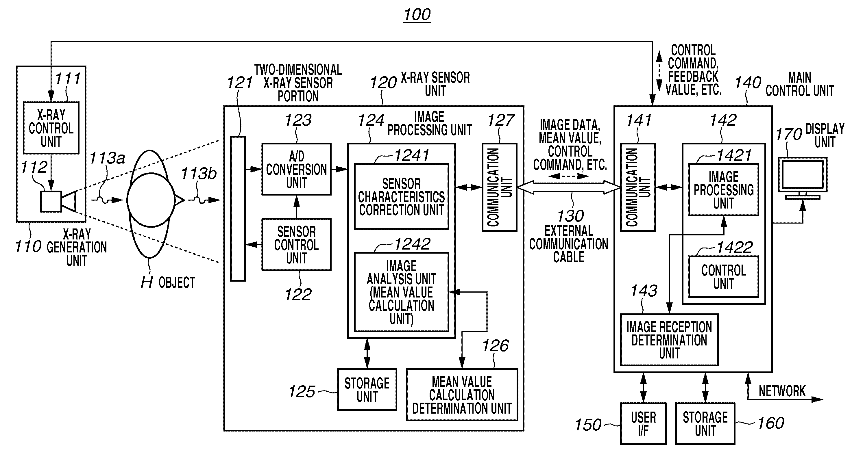
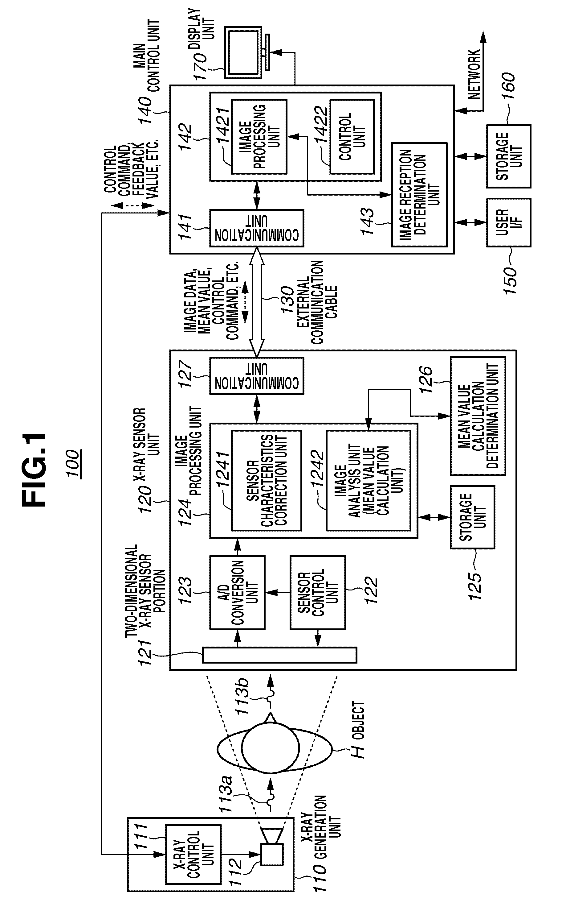
[0045]FIG. 1 is a schematic diagram illustrating an ...


PUM


Abstract

A radiation imaging system includes a radiation sensor unit and a main control unit. The radiation sensor unit includes, a radiation sensor that detects the radiation image based on the radiation ray that passes through the object, a sensor characteristics correction unit that performs sensor characteristics correction on the radiation image based on image reception characteristics of the radiation sensor, an image analysis unit that analyzes the radiation image in which the sensor characteristics correction has been performed by the sensor characteristics correction unit and calculates an analysis parameter, and a transmission unit that transmits the analysis parameter as a gradation conversion parameter and the radiation image which has been subjected to the sensor characteristics correction to the main control unit. The main control unit includes, a reception unit that receives the gradation conversion parameter and the radiation image which has been subjected to the sensor characteristics correction, and a gradation conversion processing unit that performs gradation conversion processing on the radiation image which has been subjected to the sensor characteristics correction using the gradation conversion parameter.

Description

BACKGROUND OF THE INVENTION[0001]1. Field of the Invention[0002]The present invention relates to a radiation imaging system capable of capturing a radiation image of an object using a radiation ray that passes through the object, a control method of the system, and a program used for causing a computer to execute the control method.[0003]2. Description of the Related Art[0004]An X-ray imaging apparatus is used for capturing an image using X-ray which is one type of radiation rays. In recent years, a digital X-ray imaging apparatus using a photoelectric conversion element has been used in acquiring intensity distribution of an X-ray beam that passed through an object. The digital X-ray imaging apparatus is considered advantageous over a conventional film-type imaging apparatus in that it can produce images with high sensitivity and better image quality. Further, since the images captured by the digital X-ray imaging apparatus are stored in digital data, various types of image process...

Claims


Application Information

Patent Timeline
Patent Type & Authority Applications(United States)
IPC IPC(8): H05G1/64
CPCA61B6/583
Inventor KONISHI, SHIMPEI
Owner CANON KK
Why Eureka
Try Eureka