Installation of processing units into a stored program controlled system wherein the component processing units are interconnected via free space optics

a processing unit and stored program technology, applied in the direction of optics, instruments, optical elements, etc., can solve the problems of major malfunction, difficult installation, maintenance and modification of wiring,

Inactive Publication Date: 2006-09-19
LUCENT TECH INC +1
View PDF14 Cites 10 Cited by
  • Summary
  • Abstract
  • Description
  • Claims
  • Application Information

AI Technical Summary

Problems solved by technology

One minor error may cause a major malfunction.
Therefore, a problem in the art is interconnecting processing units in a stored program controlled processing system with extensive wiring which is difficult to install, maintain and modify.

Method used


Image

  • Installation of processing units into a stored program controlled system wherein the component processing units are interconnected via free space optics
  • Installation of processing units into a stored program controlled system wherein the component processing units are interconnected via free space optics
  • Installation of processing units into a stored program controlled system wherein the component processing units are interconnected via free space optics

Examples


Embodiment Construction

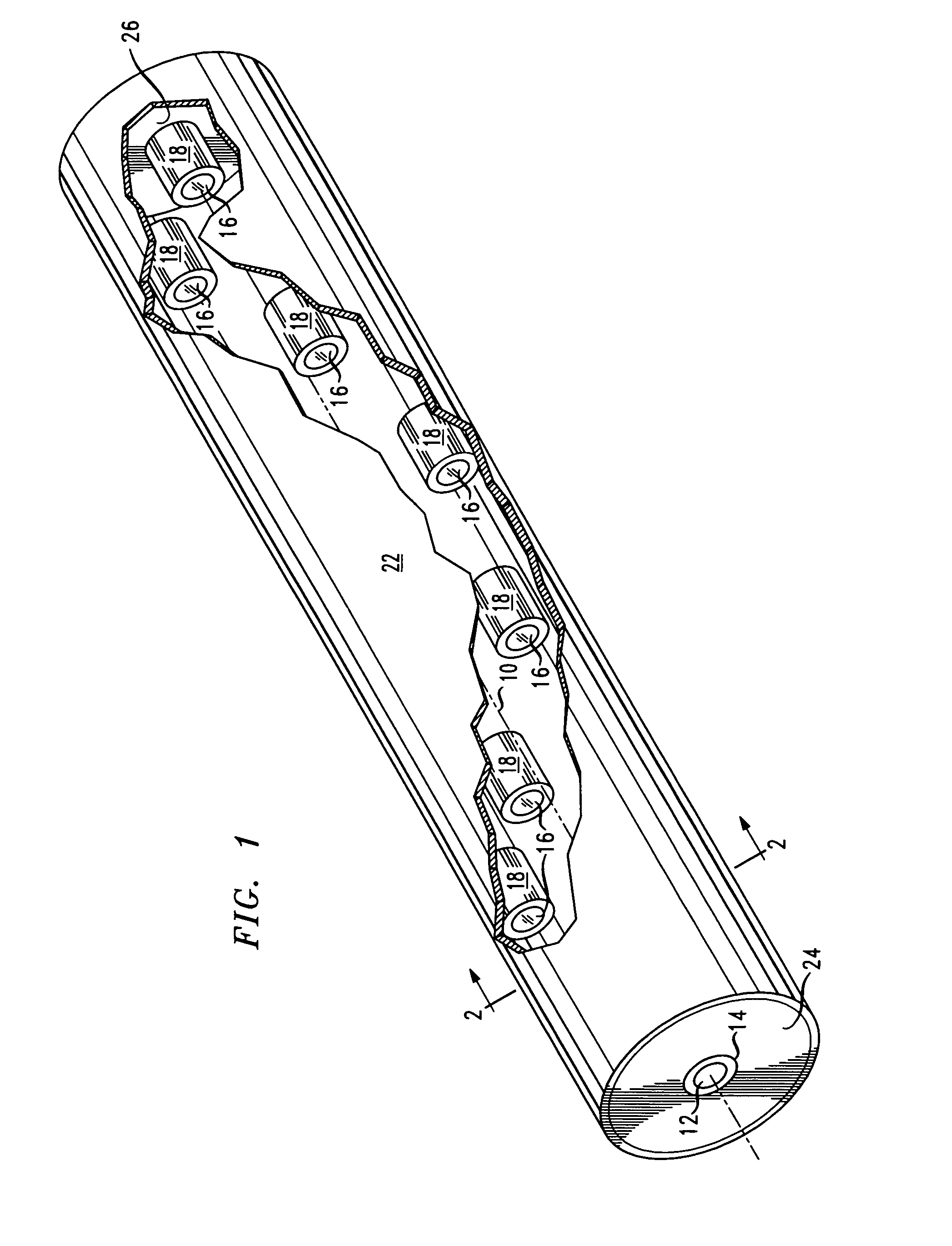
[0027]Turning to FIG. 1, a perspective view of a free space beam line 10 according to one exemplary embodiment of this invention is shown. According to this exemplary embodiment, a free space beam line 10 is generated by a transmitter 12 within a transmitting probe 14 which projects optically encoded signals, as will be described below in connection with FIGS. 3 and 4. Transmitting probe 14 produces a beam line 10 of desired diameter along the length of its path.

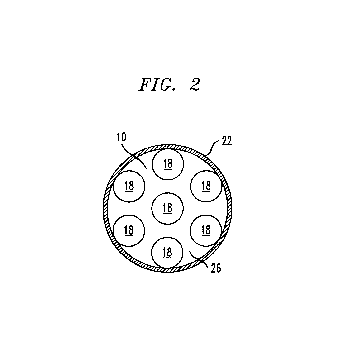
[0028]A plurality of receivers 16 within receiving probes 18 are distributed throughout beam line 10 along the outer periphery in the form of a spiral or helix, in this exemplary embodiment. Other possible configurations of probes along the beam line will be apparent to one skilled in the art after studying this disclosure. Receiving probes 18 are distributed in a helix in this exemplary embodiment so that there is a minimal amount of shadowing; that is, one receiving probe 18 being in the shadow of a previous receiving prob...


PUM


Abstract

Internal communication signals in a stored program controlled system comprising a plurality of units configured to process signals are provided by an optical beam line which is proximal to all of the plurality of units. The beam line is configured to contain optically encoded signals, which comprises signals transmitted between and / or among the plurality of units. Each unit includes a probe for injecting optically encoded signals in the beam line and / or and for receiving optically encoded signals from the beam line. Processing units include at least one aperture for passage of the beam line. Processing units may also include a movable portion that is moved during installation of the processing unit and then replaced after the main body is in place.

Description

CROSS-REFERENCE TO RELATED APPLICATIONS[0001]This application is related to U.S. patent application Ser. No. 09 / 932,703 C. C. Byers, entitled “Interconnecting Processing Units of a Stored Program Controlled System Using Free Space Optics”, filed concurrently herewith and commonly assigned to Lucent Technologies Inc., and incorporated by reference herein, with priority claimed for all commonly disclosed subject matter.[0002]This application is also related to U.S. patent application Ser. No. 09 / 932,704 C. C. Byers, entitled “Interconnecting Processing Units Of A Stored Program Controlled System Using Time Division Multiplexed Free Space Optics”, filed concurrently herewith and commonly assigned to Lucent Technologies Inc., and incorporated by reference herein, with priority claimed for all commonly disclosed subject matter.[0003]This application is also related to U.S. patent application Ser. No. 09 / 932,705 C. C. Byers, entitled “Interconnecting Processing Units Of A Stored Program C...

Claims


Application Information

Patent Timeline
Patent Type & Authority Patents(United States)
IPC IPC(8): H04B10/00G02B6/28G02B6/43
CPCH04B10/801G02B6/2804G02B6/43
Inventor BYERS, CHARLES CALVINHATCHER, DANIEL RAYMOND
Owner LUCENT TECH INC
Why Eureka
Try Eureka