Toner supplying apparatus and image forming apparatus

a technology of toner supplying apparatus and image forming apparatus, which is applied in the direction of electrographic process apparatus, instruments, optics, etc., can solve the problems of small amount of toner falling due to vibration, insufficient toner being charged, and extremely difficult to perfectly prevent toner from scattering, so as to prevent the content of toner in a developing device

Inactive Publication Date: 2006-09-19
CANON KK
View PDF13 Cites 56 Cited by
  • Summary
  • Abstract
  • Description
  • Claims
  • Application Information

AI Technical Summary

Benefits of technology

[0025]Another object of the present invention is to provide a toner supplying apparatus capable of preventing the toner content in a developing device from locally increasing to an extremely high level even if a large amount of toner is discharged from the first toner chamber of the toner supplying apparatus.

Problems solved by technology

On the other hand, moving the toner reception hole 105a too far in the direction indicated by an arrow mark B creates the problem that the toner fails to be sufficiently charged by the time it reaches the development chamber 105b.
However, in the case of this structural arrangement, when mounting or dismounting the developing apparatus 100, which is a unit removably mountable in the main assembly of an image forming apparatus, a small amount of toner falls due to vibrations, no matter how small the vibrations are.
Obviously, it is extremely difficult to perfectly prevent toner from scattering, by the provision of the shutters.
However, even if these shutter mechanisms are provided, it is impossible to avoid the problem that a small amount of toner scatters during the mounting or dismounting of the developing apparatus 100.
This scattering of toner has been one of the essential causes of the soiling of the operator's hands, dirtying of the surroundings, and / or degradation of the image forming apparatus.
However, if the mixture of the freshly supplied toner and the developer which was in the stirring chamber 105c fails to be sufficiently stirred, and reaches the development chamber 105b before it becomes uniform in toner content, an image which is not uniform in density is formed.
This solution, however, contradicts the effort for reducing the time necessary for image formation.
In recent years, this contradiction has become one of the largest technical problems, because the desire to increase the speed of an image forming apparatus has become extremely strong in recent years.

Method used


Image

  • Toner supplying apparatus and image forming apparatus
  • Toner supplying apparatus and image forming apparatus
  • Toner supplying apparatus and image forming apparatus

Examples


embodiment 1

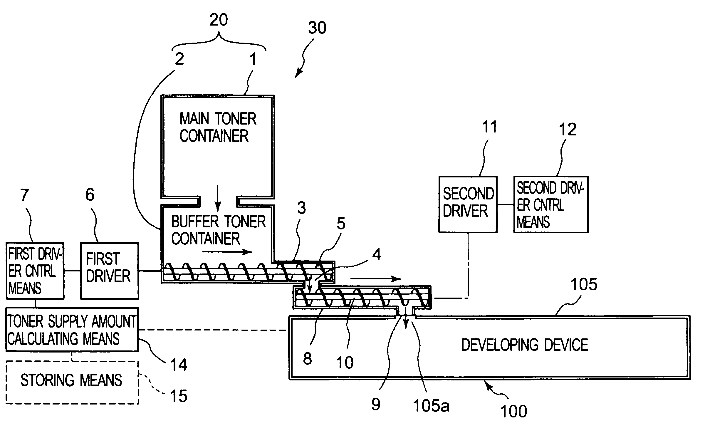
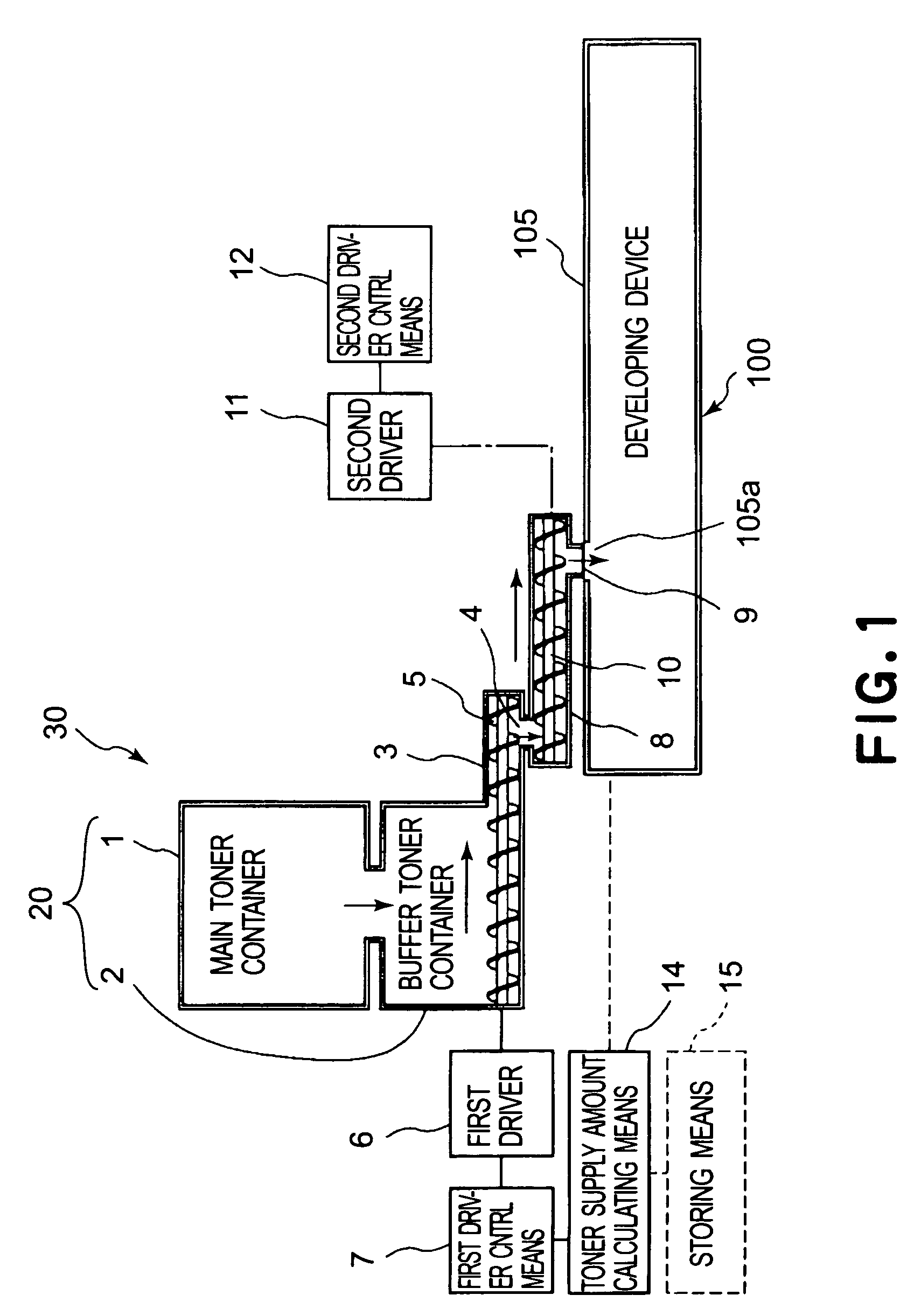
[0035]Referring to FIG. 1, a typical image forming apparatus which employs a toner supplying apparatus in accordance with the present invention, will be described regarding its general structure. In this embodiment, the present invention is embodied in the form a toner supplying apparatus employable by such an image forming apparatus as an electrophotographic copying machine, a laser printer, a facsimile machine, etc. However, this embodiment is not intended to limit the scope of the present invention in terms of the apparatus to which the present invention is applicable. It should be understood that the present invention is applicable to a wide range of electrophotographic and electrostatic image forming apparatuses.

[0036]The image forming apparatus 110 has an electrophotographic photosensitive member 111 (photosensitive drum) as an image bearing member in the form of a rotational drum. The photosensitive drum 111 is rotated in the direction indicated by an arrow mark while being u...


PUM


Abstract

A toner supply apparatus includes a first toner container; a first feeding member for feeding toner in the first toner container; a second toner container for receiving the toner from the first toner container; a second feeding member for feeding toner in the second toner container; a third toner container, detachably mountable relative to a main assembly of the toner supply apparatus, for receiving in the toner from the second toner container; wherein when the toner is supplied into the third toner container, the first feeding member is driven in accordance with a toner supply amount, and the second feeding member is substantially continuously driven irrespective of the toner supply amount.

Description

FIELD OF THE INVENTION AND RELATED ART[0001]The present invention relates to a toner supplying apparatus employed by a copying machine, a printer, a facsimileing machine, etc., which form an image with the use of an electrophotographic or electrostatic recording method. It also relates to an image forming apparatus.[0002]As the developing method employed by such an image forming apparatus as the abovementioned ones, the following method has been known: Dry developer as developing agent is borne on the peripheral surface of a developer bearing member (developing means), and is delivered by the developer bearing member to the immediate adjacencies of the peripheral surface of an image bearing member, which is bearing an electrostatic latent image, so that as alternating voltage is generated between the image bearing member and developer bearing member, the electrostatic latent image is developed into a visible image. It has been a common practice to use a development sleeve and a phot...

Claims


Application Information

Patent Timeline
Patent Type & Authority Patents(United States)
IPC IPC(8): G03G15/08
CPCG03G15/0868G03G15/0886G03G15/0893G03G15/0879G03G2215/0685G03G2215/0692
Inventor NISHITANI, HITOSHI
Owner CANON KK
Why Eureka
Try Eureka