Method and apparatus for sealing high pressure tubes

Inactive Publication Date: 2006-09-26
FRY MICHAEL E
View PDF11 Cites 9 Cited by
  • Summary
  • Abstract
  • Description
  • Claims
  • Application Information

AI Technical Summary

Benefits of technology

[0008]In one embodiment, a device for sealing a tube is disclosed including a plug having at least two annular plug wings made of a shape-memory alloy, the at least two annular plug wings formed substantially perpendicular to an axis of the plug and having an unbent diameter greater than an inner diameter of the tube. The at least two annular plug wings are bent in opposite directions when in a martensite phase and have a bent diameter less than the inner diameter of the tube.
[0009]In another embodiment, a method of method for sealing a tube is disclosed including selecting a plug having at least two annular plug wings and made of a shape-memory alloy; the at least two annular plug wings are formed substantially perpendicular to an axis of the pl

Problems solved by technology

In high pressure applications, especially where high pressure steam is present, conventional methods of sealing high pressure tubes are not always practical.
Welding is one method, but tight working spaces often make it difficult to weld an individual high-pressure tube.
Cre

Method used


Image

  • Method and apparatus for sealing high pressure tubes
  • Method and apparatus for sealing high pressure tubes
  • Method and apparatus for sealing high pressure tubes

Examples


second embodiment

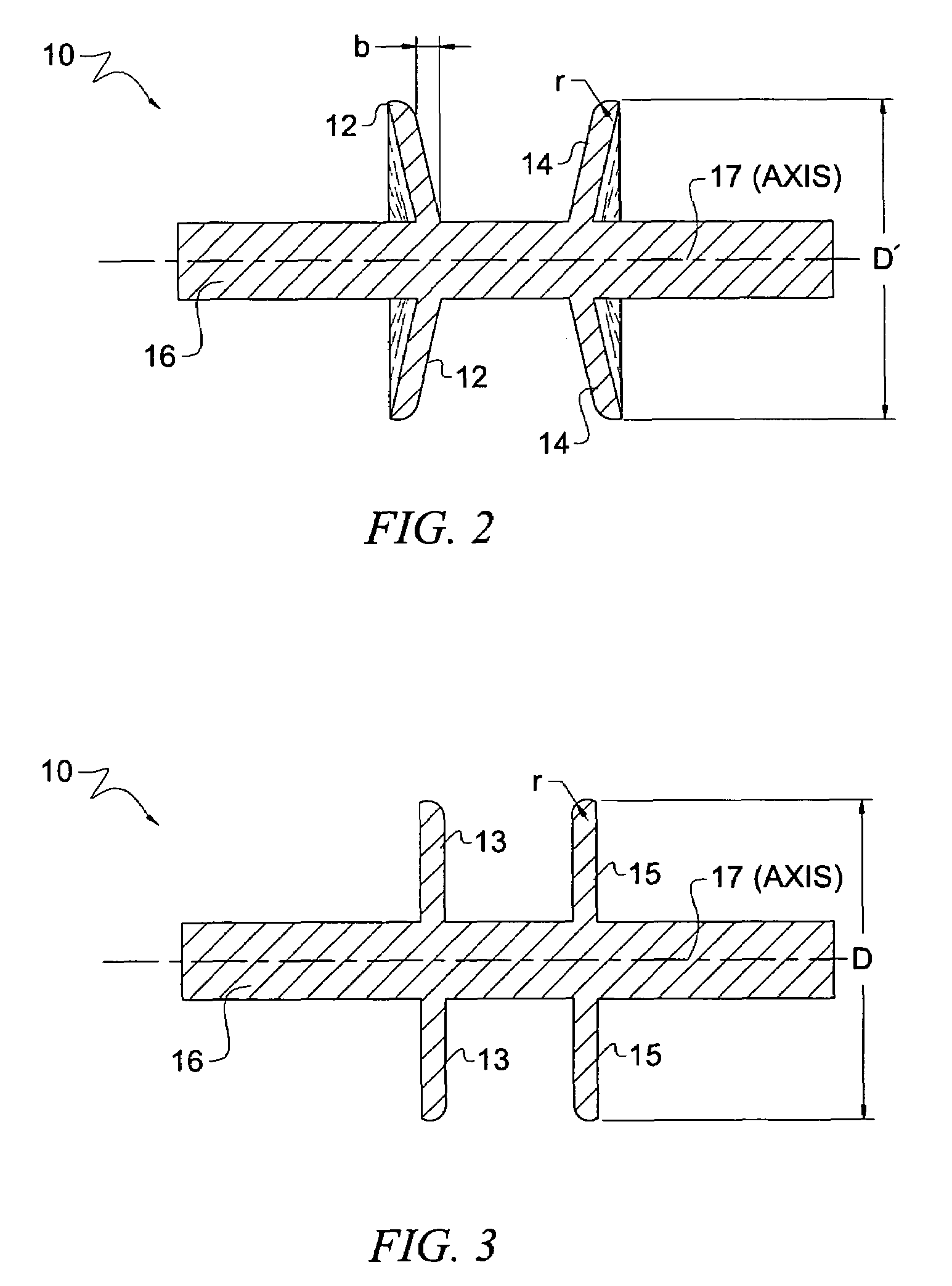
[0036]Referring to FIG. 6, FIG. 6a and FIG. 7, a plug of the present invention is shown. The plug 11 is shown in its deformed state in FIG. 6, ready for insertion into a tube and the plug 11 is shown in its pre-deformed state or restored state in FIG. 7. The plug 11 in FIG. 6a is shown in its deformed state. In this embodiment, the pairs of wings are bent in opposite directions, instead of bending each pair in the same direction as in FIG. 6. The plug 11 is made of the same materials as the plug 10 of FIG. 2 and FIG. 3, but has four plug wings 12 / 13 / 14 / 15 instead of two plug wings of plug 10. In its base shape, the plug walls 13 / 15 are substantially perpendicular to the plug shaft 16 along its axis 17 as in FIG. 7. During manufacture, the plug 11 is cooled to the martensite finish temperature of the alloy using any method known in the industry to achieve the temperature required. The martensite finish temperature depends upon the exact alloy composition, usually −150° Fahrenheit. On...

first embodiment

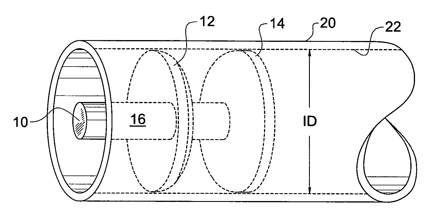
[0039]Referring now to FIG. 8 and FIG. 9, a plug of the present invention is shown in its deformed state being inserted into a tube. The plug 10 has wings 12 / 14 and a shaft 16. The top wings 12 are bent in an upward direction and the bottom wings 14 are bent in a downward direction, so that when there austenite finish temperature is reached, the wings 12 / 14 apply a force towards each other. The plug 10 has a diameter that is slightly smaller than the inner diameter ID of the tube 20 so it can be inserted within the inner wall 22 of the tube 20. Once inserted, the plug 10 is heated until it reaches its austenite finish temperature and the wings 12 / 14 try to restore to their original shape, applying pressure to the inner wall 22 of the tube 20. FIG. 9 shows how the plug 10 looks as it is inserted into the tube 20. It can be seen that there is a gap between the outer surface of the plug wing 12 and the inner surface of the tube wall 22. This gap gets closed when the plug 10 is heated t...


PUM

PropertyMeasurementUnit
Temperatureaaaaaaaaaa
Fractionaaaaaaaaaa

Abstract

A plug for sealing high pressure tubes is made from a memory-shape alloy. The plug is formed having a diameter greater than the inner diameter of the tube and is shaped by cooling to its martensite finish temperature and bending its wings in opposing directions such that at a later time, it will fit within the tube. After insertion into the tube, the plug is heated to its austenite finish temperature, restoring its wings to almost their original shape, thereby exerting force onto the tube walls, sealing the tube from leakage.

Description

BACKGROUND OF THE INVENTION[0001]1. Field of the Invention[0002]The present invention relates generally to a method and apparatus for sealing tubes and more particularly to sealing high-pressure tubes such as used in heat exchangers.[0003]2. Description of the Related Art[0004]In high pressure applications, especially where high pressure steam is present, conventional methods of sealing high pressure tubes are not always practical. Welding is one method, but tight working spaces often make it difficult to weld an individual high-pressure tube.[0005]Various plugs have been used successfully, each with their limitations. The particular problems encountered in the industry are very well articulated in prior U.S. Pat. No. 4,976,307 and U.S. Pat. No. 5,189,789, both of which are hereby incorporated by reference in their entirety. The present invention is an improvement over the embodiments disclosed in these prior patents. A method of repairing a leaking feed water heater is to seal both...

Claims


Application Information

Patent Timeline
IPC IPC(8): F16L55/10
CPCF16L55/11Y10T29/49352
Inventor FRY, MICHAEL E.
Owner FRY MICHAEL E
Why Eureka
Try Eureka