Infusion device and method for infusing material into the brain of a patient

a technology of infusion device and patient brain, which is applied in the direction of multi-lumen catheters, other medical devices, catheters, etc., can solve the problems of large dead space of catheters, limited reliability and reproducibility of infusions, and significant brain damage, etc., and achieve the effect of effective and accurate us

Active Publication Date: 2010-07-29
MEDTRONIC INC
View PDF19 Cites 1 Cited by
  • Summary
  • Abstract
  • Description
  • Claims
  • Application Information

AI Technical Summary

Benefits of technology

[0008]Accordingly, the present invention relates to an infusion device that can be utilized effectively and accurately to infuse a minute quantity of a liquid at an extremely low flow rate into a desired target area of the brain of a patient.
[0011]A hollow, flexible infusion fiber is positioned within the lumen of the single lumen guide catheter, or within one of the lumens in the event a multi-lumen guide catheter is utilized. The flexible infusion fiber also has a distal end and a proximal end. The infusion fiber is dimensioned to be snugly fitted within and axially movable or fixed in position within the guide catheter and has its proximal end extending outwardly from the proximal end of the guide catheter and with the distal end of the infusion fiber extending outwardly from the distal end of the guide catheter. When the infusion fiber is fixed and immoveable within the guide catheter, the distal end is located a fixed distance from the distal end of the guide catheter. If axially movable within the guide catheter, the distal end of the infusion fiber can be extended outwardly to the desired location a distance from the distal end of the guide catheter. In either event, the infusion fiber is of a lesser diameter than the guide catheter so that the tissue to be infused need not be entered by the larger guide catheter, minimizing tissue trauma.
[0013]Accordingly, the infusion device can allow the flexible infusion fiber to enter the brain, particularly deep brain structures, and the critical component, the flexible end of the infusion fiber that extends the desired distance outwardly from the distal end of the guide catheter, can be movable within the brain to float therein. The distal end of the infusion fiber, therefore, is a very fine component that extends outwardly from the larger guide catheter component at a distance determined by the physician placing the infusion device.
[0014]Due to the particular dimensions of the infusion fiber, there is very little dead space and the extremely small size minimizes the possibility that the infused fluid tracks back along the infusion fiber track, that is, the infusion of fluid is restricted to the particular target area which, as explained, can be as small as 1 mm3, or as large as several cubic centimeters. The larger guide catheter, whether or not the infusion fiber is fixed, provides stability and strength (protecting the fragile inner infusion fiber) as well as imaging capabilities, but only enters the tissue proximal to the target and thus does not significantly damage the target tissue.
[0015]Of importance, also, is that the infusion device, once in place, need not be stabilized by attachment to the skull itself or a stereotactic frame, since it is designed to float in the brain. The stabilization of the infusion device can, therefore, simply be carried out by the aforedescribed suturing, or other means of affixing, the guide catheter to the scalp. That floating effect also avoids the microtrauma and / or hemorrhage associated with the more rigid devices and the floating effect allows the distal end of the infusion fiber to move in relationship to the brain during physiological movement associated with coughing, sneezing, respiration, physical activity or the like. Nonetheless, the more substantial proximal guide catheter protects the fragile inner infusion fiber, permitting fixation to the skull and / or scalp to prevent withdrawal of the catheter from the target, which can be a problem common to current infusion systems which were never designed for infusion into solid tissue such as the brain. Potential fixation methods include, but are not limited to, fixation to the skull near the burr hole with a metal plate, such as a titanium plate, fixation with a plastic capping system placed within the burr hole, or externalization through the scalp and suturing of the guide catheter to the scalp.

Problems solved by technology

Such catheter has, however, a rather large dead space due to the very dimensions of that catheter.
This large dead space limits reliability and reproducibility of infusions, particularly for small volumes of fluid, due to the large errors and insensible losses inherent in catheters with dead spaces which are significantly greater that the actual volume of fluid to be infused.
In addition, large catheters cause significant damage to the brain in the area of infusion.
This not only can confound therapeutic results, it can also limit the effectiveness and reliability of the infusion.
This creates a dilemma, however.
Although fine catheters are desirable, very fine systems do not usually have the resiliency or strength to withstand long term use.
This would be particularly true for catheters which would be externalized and attached to an infusion pump, since these would be particularly subject to damage by the patient or by routine healthcare workers.
Clamping very fine catheters in fixation devices, usually requiring catheters to be bent at extreme angles, would also likely break or obstruct a fine catheter.
Similarly, an extremely fine catheter is difficult to visualize by imaging, even when impregnated with a contrast agent, due to resolution limits of current imaging systems.
Current systems for infusion are largely designed for infusion into fluid channels, such as intravascular or intrathecal infusion, and thus are limited in one of more of the criteria outlined above.

Method used


Image

  • Infusion device and method for infusing material into the brain of a patient
  • Infusion device and method for infusing material into the brain of a patient
  • Infusion device and method for infusing material into the brain of a patient

Examples


Embodiment Construction

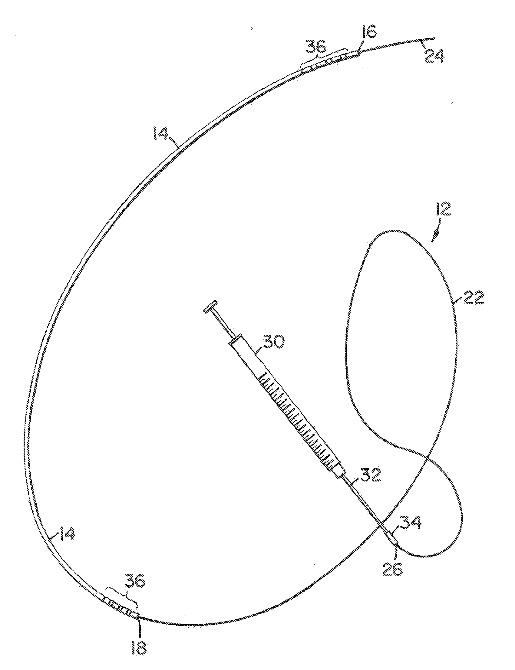
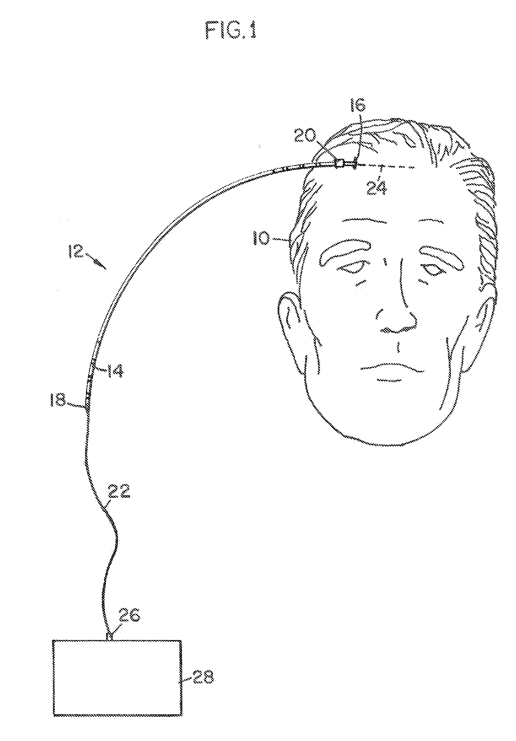
[0025]Referring now to FIG. 1, there is shown a front view of the skull 10 of a patient illustrating the operative position of an infusion device 12 constructed in accordance with the present invention. As can be seen, there is a flexible guide catheter 14 that has a distal end 16 and a proximal end 18. In the use of the infusion device 12, as will be later explained, the distal end 16 is preferably located within the interior of the skull 10 of the patient whereas the proximal end 18 can be normally located exterior of the patient, or also remain under the scalp.

[0026]Once positioned as shown in FIG. 1, the guide catheter 14 can be affixed to the scalp of the patient by means of one or more sutures 20 or by other methods. The actual location of the distal end 16 of the guide catheter 14 can be achieved through the use of a stereotactic frame, by frameless means or even manually.

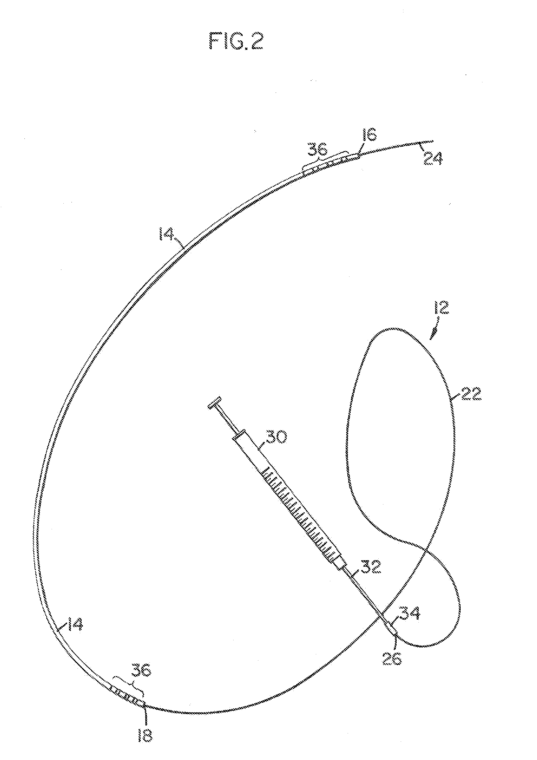
[0027]The infusion device 12 also includes a flexible infusion fiber 22 that is threaded within a lumen o...


PUM


Abstract

A fluid infusion device and a method of using the same. The device includes an outer, flexible guide catheter having a distal end for introduction beneath the skull of a patient and a proximal end remaining external of the patient. A flexible infusion fiber is located within the guide catheter and has a distal end extending outwardly from the guide catheter to be located in a target area within the patient's brain. The infusion fiber can be fixed or axially movable within the guide catheter. In the latter embodiment, the proximal end of the infusion fiber extending outwardly from the guide catheter can be manipulated to locate the distal end of the infusion fiber in the target area. An infusion pump is connected to the proximal end of the infusion fiber to infuse a minute quantity of fluid at an extremely low flow rate into the brain of the patient.

Description

RELATED APPLICATION[0001]This application is (i) a divisional application of U.S. patent application Ser. No. 11 / 280,965, filed on Nov. 16, 2005, which application published as US 2006 / 0129126 on Jun. 15, 2006, and (ii) claims the benefit of priority to U.S. Provisional Patent Application Ser. No. 60 / 629,759, filed Nov. 19, 2004 and entitled “INFUSION DEVICE AND METHOD FOR INFUSING MATERIAL INTO THE BRAIN OF A PATIENT”.BACKGROUND[0002]The present invention relates to infusion devices for introducing fluids into a patient and, more particularly, to an infusion device and method of infusing minute volumes of liquid at extremely low flows into the brain of a patient.[0003]There are certain procedures carried out on a patient where extremely minute, sub-milliliter amounts of fluids or suspensions are directly infused into the brain of the patient and such fluids can include therapeutic drugs or biological material including peptides, proteins, viral vectors, DNA, RNA and other nucleic a...

Claims


Application Information

Patent Timeline
Patent Type & Authority Applications(United States)
IPC IPC(8): A61M5/14A61M25/00
CPCA61M5/141A61M5/14244A61M25/00A61M25/0026A61M2210/0693A61M25/0662A61M2005/1404A61M2025/0213A61M2025/0681A61M25/02
Inventor KAPLITT, MICHAEL G.DURING, MATTHEW J.
Owner MEDTRONIC INC
Why Eureka
Try Eureka