

Socket used to house female plugs and micro-relays
- Summary
- Abstract
- Description
- Claims
- Application Information
AI Technical Summary
Benefits of technology
Problems solved by technology
Method used
Image

Examples
Embodiment Construction
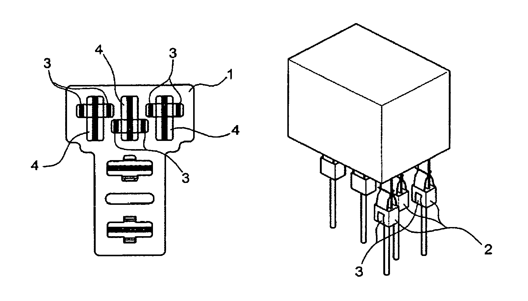
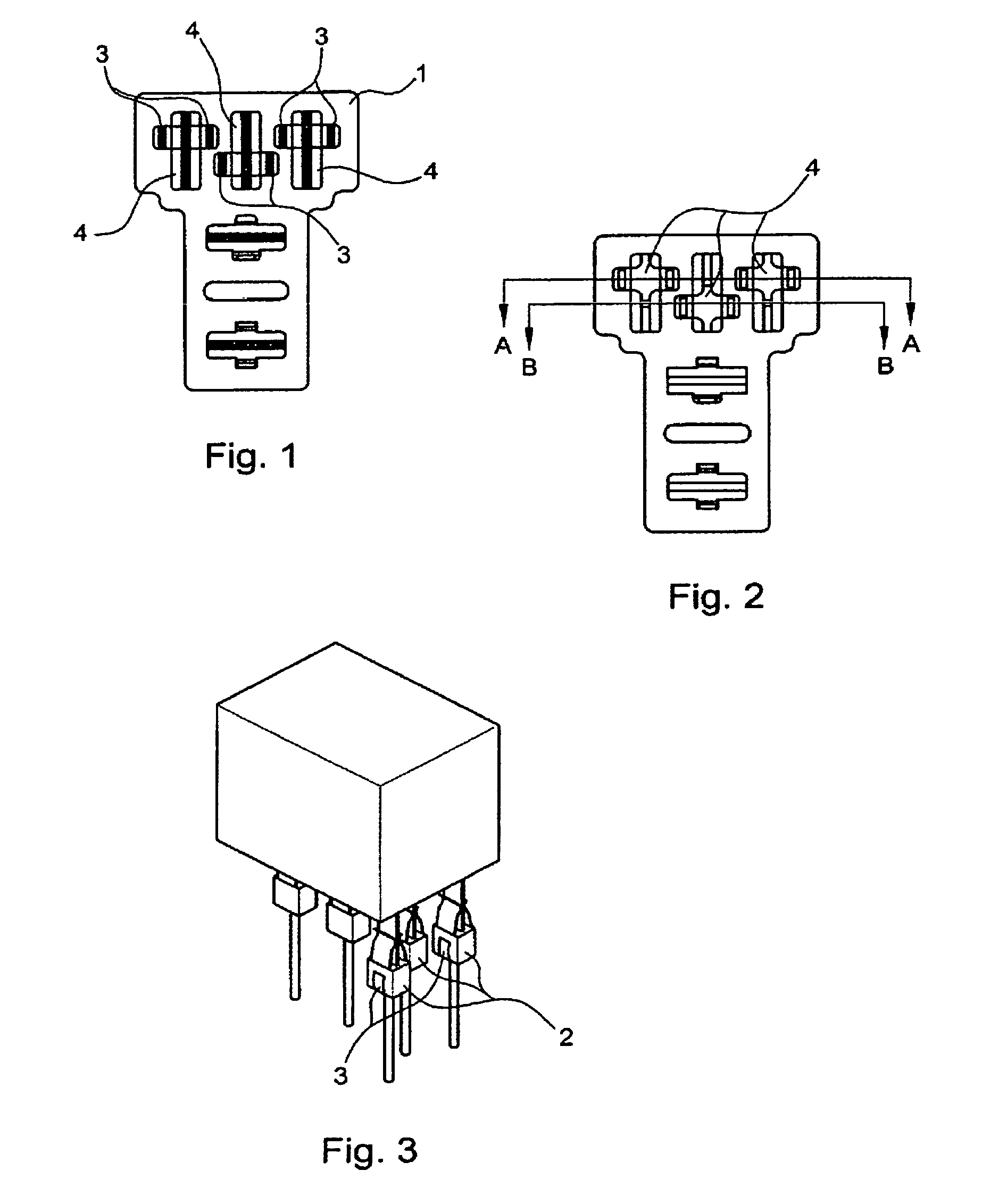
[0016]According to the embodiment example shown, the plugboard for housing sockets and micro-relays illustrated in this preferred embodiment is a plugboard with the traditional dimensions of the ones used for housing connectors suitable for mounting, sockets or micro-relays, composed of a base (1) having a plurality of connector mounting holes (4) and a plurality of connectors (2). The distribution of the connectors (2), ensuring the connection with traditionally used means with no need to modify the design of the traditional connectors (2) suitable for mounting sockets or micro-relays, is provided with three holes (4), every other hole (4) being shifted 180°.
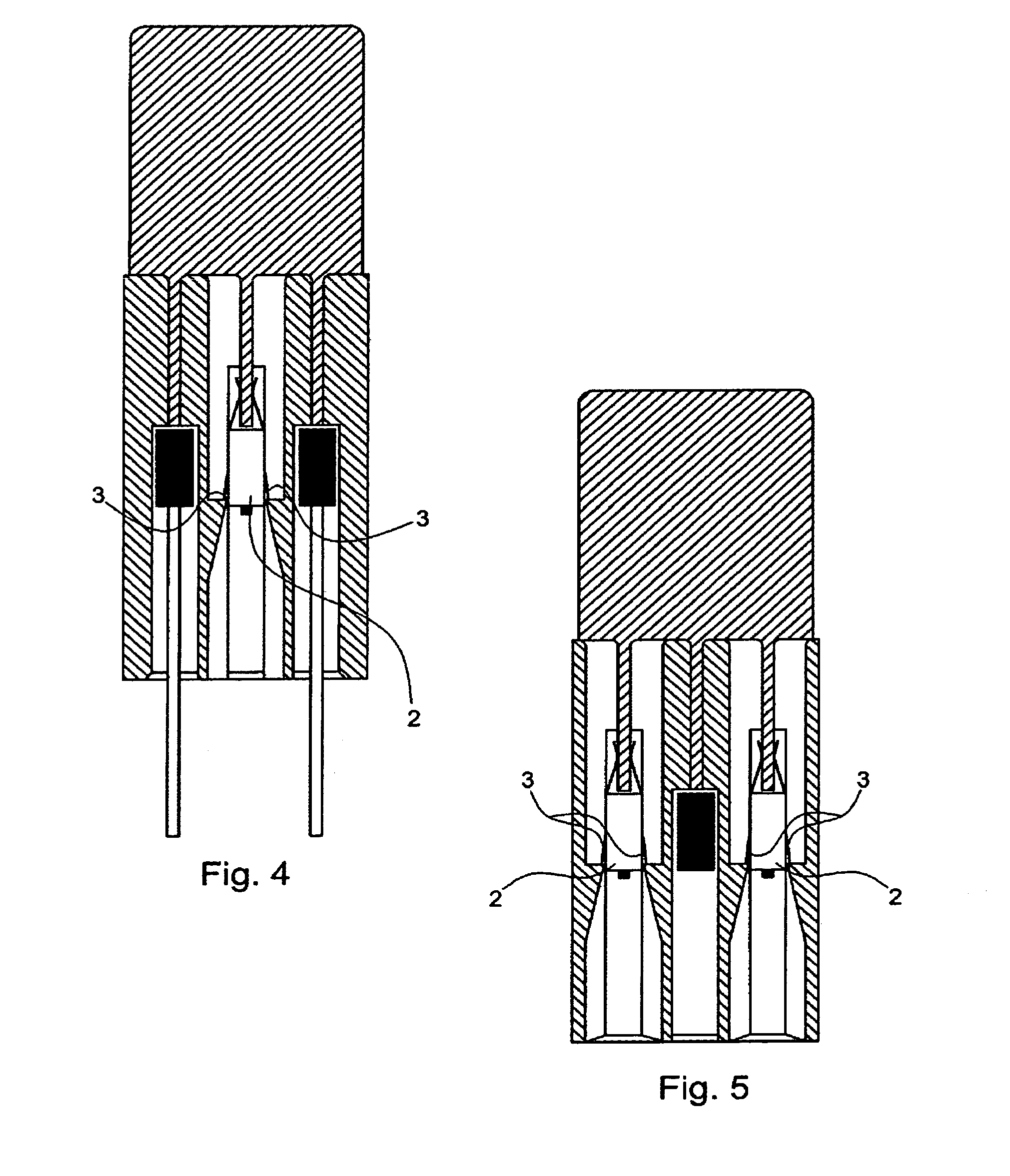
[0017]Thus, in the plugboard itself, the two pins (3) of each of the connectors (2) can be opened, ensuring the connection between plugboard and connectors housed in it.
[0018]Although the preferred embodiments of the present invention has been disclosed, various changes and modifications may be made without departing from the s...
PUM
 Abstract
Description
Claims
Application Information