Video signal processing circuit, viewfinder apparatus, television camera, and image monitor apparatus

Inactive Publication Date: 2006-09-26
SONY CORP +1
View PDF15 Cites 1 Cited by
  • Summary
  • Abstract
  • Description
  • Claims
  • Application Information

AI Technical Summary

Benefits of technology

[0014]When the above video signal processing circuit is applied to a viewfinder apparatus for a television camera, a visual field frame can be clearly displayed, thus improving visibility in focusing.
[0015]The video signal

Problems solved by technology

These components are difficult to be miniaturized.
When these components are mounted in a small apparatus, they are apt to pick up electromagnetic noise generated by peripheral devices.
Hence, the cost of such an apparatus is high.
If an amplification degree

Method used


Image

  • Video signal processing circuit, viewfinder apparatus, television camera, and image monitor apparatus
  • Video signal processing circuit, viewfinder apparatus, television camera, and image monitor apparatus
  • Video signal processing circuit, viewfinder apparatus, television camera, and image monitor apparatus

Examples


Example

[0020]The present invention will be understood from the following description of the preferred embodiments with reference to the accompanying drawings.

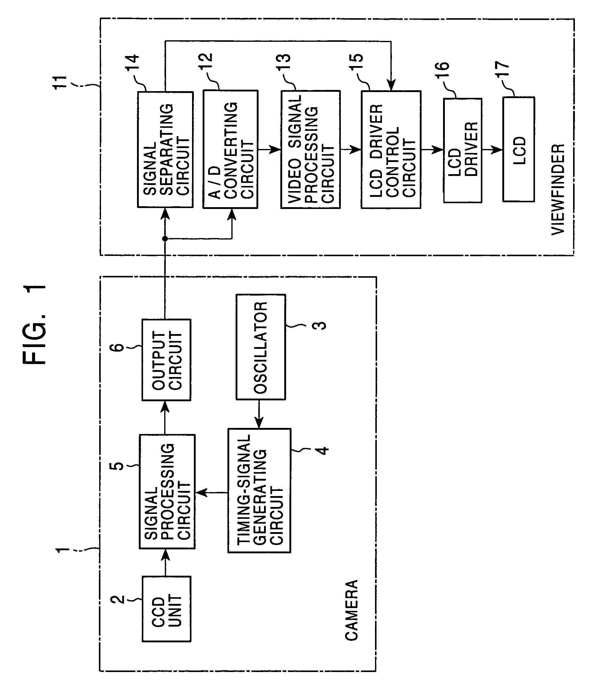
[0021]FIG. 1 is a block diagram of a television camera including a video signal processing circuit according to an embodiment of the present invention.

[0022]Referring to FIG. 1, the television camera includes a camera 1. A charge-coupled device (CCD) unit 2 captures image data obtained through a lens (not shown), which in turn is input as an electrical signal to a signal processing circuit 5 operated by a timing signal generated by an oscillator 3 and a timing-signal generating circuit 4. The electrical signal passes through an output circuit 6 and is output as a Y signal, a Pr signal, and a Pb signal in an HDTV system, or as R, G, B video signals in an NTSC / PAL system.

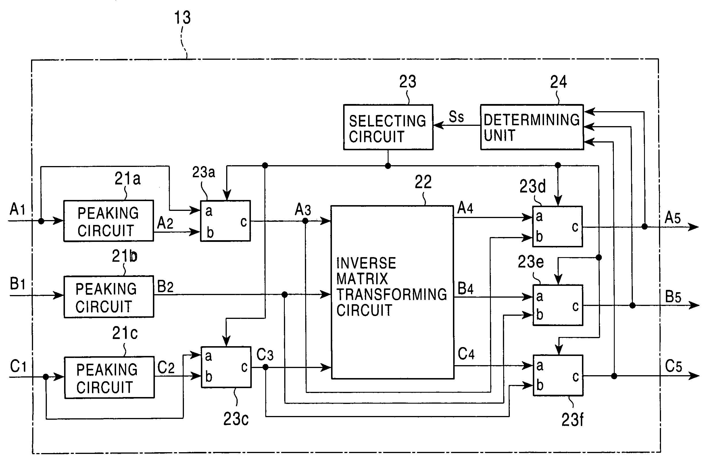
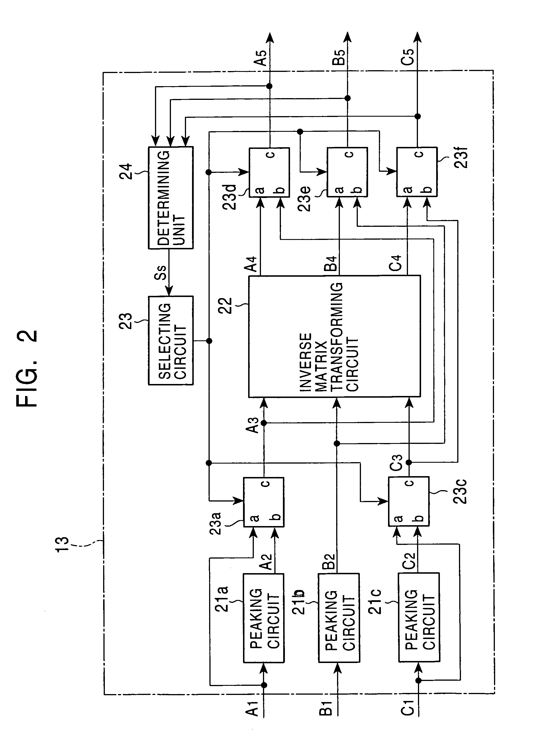
[0023]These signals are converted to digital signals by an A / D converting circuit 12 of a viewfinder 11, and the converted digital signals are input to a video signal p...


PUM


Abstract

A video signal processing circuit, which performs contour adjustment by means of digital signal processing, is applicable to a viewfinder apparatus for a television camera and an image monitor apparatus, which can be operated both in an NTSC/PAL system and an HDTV system. The video signal processing circuit includes a contour-adjusting circuit for performing contour adjustment by peaking R, G, and B signals or by peaking a Y signal in an HDTV system and for outputting at least one adjusted signal; an inverse matrix transforming circuit for separating, by performing inverse matrix transformation, the R, G, and B signals from the adjusted Y signal, a Pr signal, and a Pb signal and for outputting the separated R, G, and B signals; and a selecting circuit for selecting, in accordance with the type of input video signals, either the R, G, and B signals in which the contour adjustment is performed or the Y signal, in which the contour adjustment is performed, and the Pr signal and the Pb signal, in which the contour adjustment is not performed.

Description

BACKGROUND OF THE INVENTION[0001]1. Field of the Invention[0002]The present invention relates to video signal processing circuits in NTSC and PAL systems and in a high definition television (hereinafter referred to as “HDTV”) system, viewfinder apparatuses including the video signal processing circuits, television cameras including the viewfinder apparatuses, and image monitor apparatuses including the video signal processing circuits.[0003]2. Description of the Related Art[0004]Hitherto, video signal contour-adjusting circuits have been employed to improve the resolution of an image in a viewfinder apparatus for a television camera by enhancing the contour of the image to be captured and therefore to enable a user to easily observe the image.[0005]In general, the video signal contour-adjusting circuits separate a part of the video signal where the temporal variation is great, which in turn is amplified and added to the original signal.[0006]To this end, a method described below has...

Claims


Application Information

Patent Timeline
IPC IPC(8): H04N9/64H04N5/208H04N5/21G09G5/00H04N5/232
CPCH04N9/646H04N5/23293H04N5/208H04N23/661H04N23/63H04N25/447
Inventor SEINO, KENICHIKAMIKO, MITSUOKATSUYAMA, TOMOYASUDATE, YOSHIHIROHAGIWARA, NAOKI
Owner SONY CORP
Why Eureka
Try Eureka