Automated UV recoat inspection system and method

a fiber and automatic technology, applied in the field of fiber inspection, can solve the problems of inability to accurately detect the presence of uv recoat, the length of optical fibers that can be drawn, and the difficulty of fiber splicing,

Inactive Publication Date: 2006-09-26
CIENA
View PDF7 Cites 4 Cited by
  • Summary
  • Abstract
  • Description
  • Claims
  • Application Information

AI Technical Summary

Benefits of technology

[0010]It is an object of the present invention to provide an index for determining the stability of an interconnected fiber. It is further an object of the present invention to automate such determination. It is yet another object of the present invention to provide a system for quick, controlled data gathering for use in inspecting a fiber.

Problems solved by technology

Optical fibers are very light, very fragile, and have very small dimensions.
During their initial manufacture, there are practical limitations on the lengths of optical fibers that can be drawn.
The nature of the fibers themselves, both in the material used in their fabrication and in the minute physical dimensions involved, as well as submicron alignment requirements, make fiber splicing more difficult than conventional metallic conductor splicing.
While each of the individual steps can be performed somewhat quickly, the set-up, preparation and transfer time between the steps of the splicing process consumes a significant amount of time.

Method used


Image

  • Automated UV recoat inspection system and method
  • Automated UV recoat inspection system and method
  • Automated UV recoat inspection system and method

Examples


Embodiment Construction

[0020]The present invention will be described in detail through preferred embodiments with reference to accompanying drawings. However, the present invention is not limited to the following embodiments but may be implemented in various types. The preferred embodiments are only provided to make the disclosure of the invention complete and make one having an ordinary skill in the art know the scope of the invention. The thicknesses of various layers and regions are emphasized for clarity in accompanying drawings. Throughout the drawings, the same reference numerals denote the same elements.

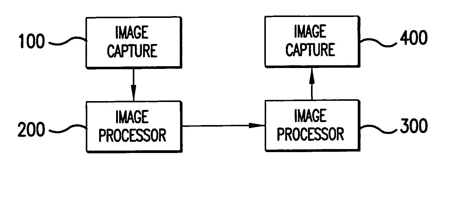
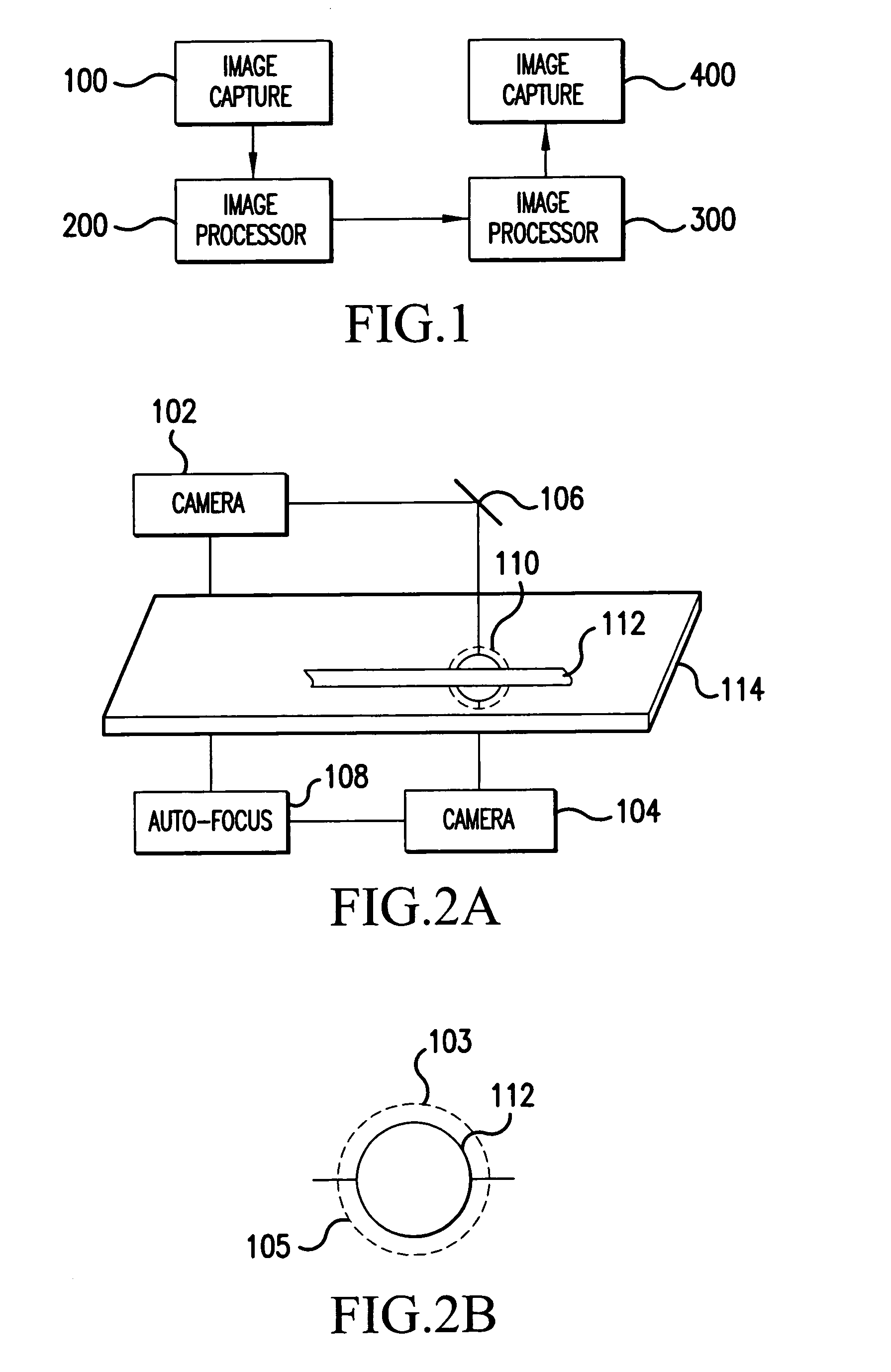
[0021]A block diagram of the inspection system of the present invention is shown in FIG. 1. An image capture unit 100 takes an image of the fiber to be inspected. This image is sent to an image processor 200, e.g., a microprocessor or central processing unit. The image processor 200 extracts any imperfections from the images, analyzes the features of these imperfections, and compares these features ...


PUM


Abstract

A camera system and automated translation system allows automatic image capture of a recoat of a fiber which has undergone a number of processes. These images may be used to automatically inspect the recoat of the fiber in accordance with objective criteria. A stability index may be determined based on the thickness of the recoat on the fiber, a uniformity of the recoat on the fiber, a depth of any surface cracks on the recoat, and a depth of any bubbles in the recoat. A desired stability index may be determined in accordance with a desired lifetime of the fiber and an intended use of the fiber.

Description

BACKGROUND OF THE INVENTION[0001]1. Field of the Invention[0002]The present invention is directed to inspecting a fiber which has under gone a series of processing steps, including UV recoating. More particularly, the present invention is directed to an automatic inspection of a fiber at the end of the processing thereof.[0003]2. Description of Related Art[0004]Optical fibers are very light, very fragile, and have very small dimensions. During their initial manufacture, there are practical limitations on the lengths of optical fibers that can be drawn. Therefore, the connections between the fibers to create longer designated lengths of fiber are accomplished by splicing. In addition, optical fibers or optical devices must be connected to pieces of terminal equipment, such as optical transmitters and optical receivers, to create functioning optical systems.[0005]Direct fiber-to-fiber splicing can be accomplished using mechanical splicing devices or by fusing the glass fiber ends toge...

Claims


Application Information

Patent Timeline
Patent Type & Authority Patents(United States)
IPC IPC(8): G06K9/00
CPCG01M11/37G01M11/088
Inventor DAR, IQBAL M.
Owner CIENA
Why Eureka
Try Eureka