

Image decompression apparatus and method
a decompression apparatus and image technology, applied in the field of image decompression apparatus and method, can solve the problems of reducing the number of pixels which can be used for display, unable to use all the pixels of the original image having high definition/resolution, and unable to completely decompress the original imag
- Summary
- Abstract
- Description
- Claims
- Application Information
AI Technical Summary
Benefits of technology
Problems solved by technology
Method used
Image

Examples
second embodiment
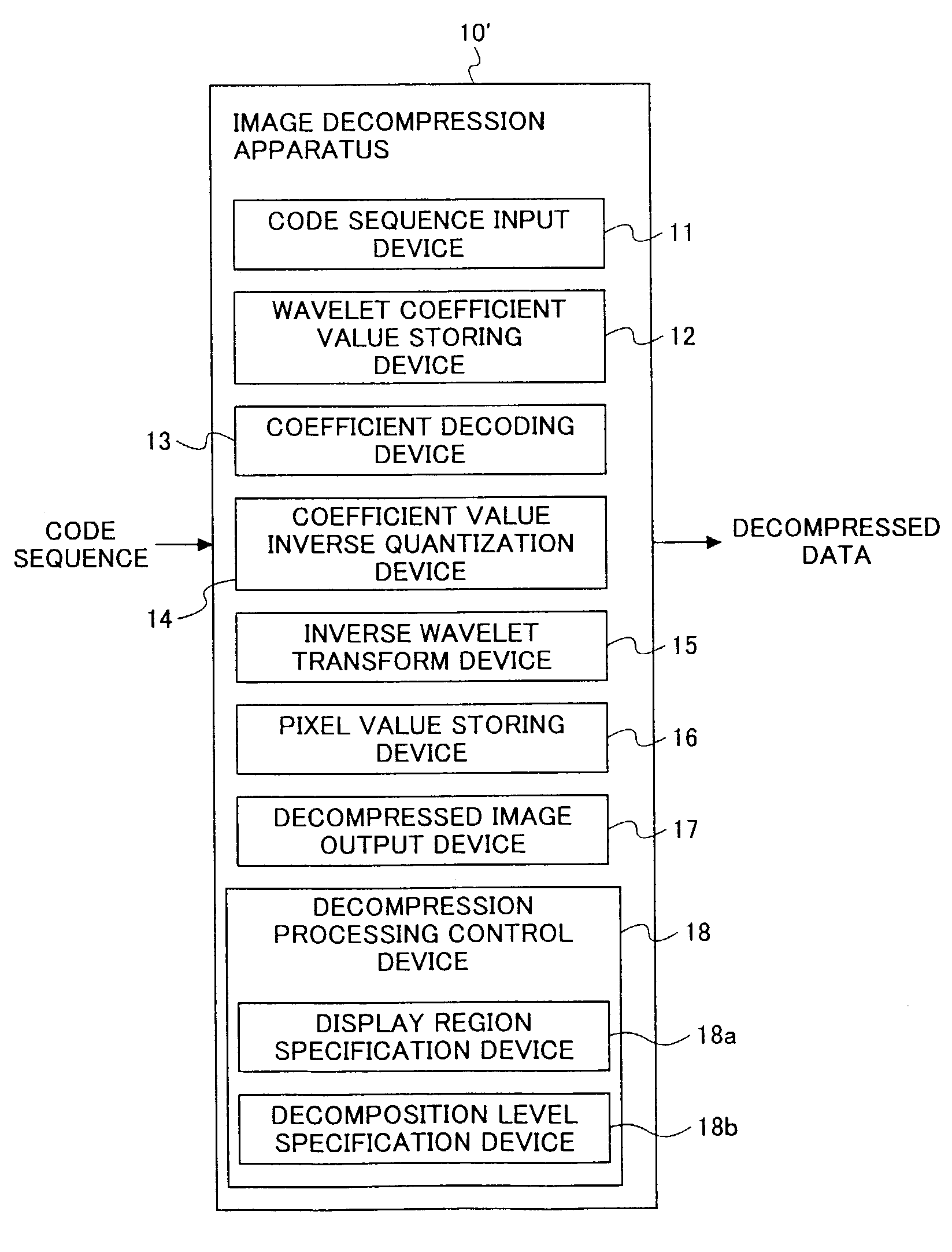
[0064]FIG. 8 illustrates a configuration of a still image decompression apparatus according to the present invention. In this embodiment, the decompression processing control device 18 as described with reference to FIG. 7 specifically includes a display region specification device 18a and a decomposition determination device 18b. The display region specification device 18a is used for specifying a display region in which a reduced image is to be displayed, on the display device in terms of pixel units for the vertical direction and the horizontal direction on the display region.
[0065]The display region specification devise 18a calculates a decomposition level such that an image obtained from wavelet coefficient values of the LL subband on the calculated decomposition level can be displayed in the specific display region. On the other hand, the decomposition determination device 18b may be used for directly specifying the decomposition level, the wavelet coefficient values of the LL...
third embodiment
[0067]In the present invention, a size change device is provided in the decompression processing control device 18 for performing size change processing on pixel values of a decompressed image, together with a device for specifying whether or not such a size change operation is to be performed. Such a size change operation is performed for fine adjustment of the image size to be displayed on the above-mentioned predetermined display region so as to provide an image size which coincides with the size of the predetermined display region.
[0068]Specifically, for the purpose of such fine adjustment in image size, interpolation processing for slightly increasing the number of pixels, or thinning out processing for slightly reducing the number of pixels of the image, each well-known, may be employed. In case the user specifies that no size change processing is to be performed, an actual size reduction rate to be applied may be determined as the power of ½ obtained automatically from a LL s...
fourth embodiment
[0072]In the present invention, a device is provided in the decompression processing control device 18 for specifying a spatial area to be decompressed, a color-space component to be decompressed, or an operation sequence / order in decompression operation. As to the specification of a spatial area to be decompressed, a spatial area to be decompressed may be specified with respect to tile units or precinct units. As to the specification of a color-space component to be decompressed, in the case where image data is expressed in a color space to include components of R (red), G (green), B (blue); Y (luminosity), U (blue color difference), V (red color difference); or Y (luminosity), Cb (blue color difference), Cr (red color difference), any one of these components may be specified as a target component to be specifically decompressed.
[0073]Thus, by specifying a specific spatial area or a specific color-space component to be decompressed, it becomes possible to effectively reduce the amo...
PUM
 Abstract
Description
Claims
Application Information