Flashing for inclined roof and method for installing the same

a technology of inclined roof and flashing, which is applied in the field of flashing, can solve the problems of difficult installation of flashings and inability to allow efficient drainage of water, and achieve the effects of convenient and efficient installation, convenient adjustment, and efficient and versatil

Active Publication Date: 2006-10-03
I C C CIE DE CHEMINEES INDS
View PDF13 Cites 43 Cited by
  • Summary
  • Abstract
  • Description
  • Claims
  • Application Information

AI Technical Summary

Benefits of technology

[0030]Thanks to its particular structure and the way it is installed, the flashing according to the invention may be installed in a very easy and efficient manner on any kind of roofs, including roofs with a corrugated structure defining downwardly oriented ridges.
[0031]In such a case, one has only to cut for indentations to be into the bottom sidewall of the base member. These indentations must be large enough to receive the ridges of the corrugated roof. However, they can easily be “adjusted” to fit any kind of corrugated roofing material whatever be the form of their ridges (square, round, sinusoidal, etc.).
[0032]The same flashing can also be installed in an easy and efficient way on an inclined metal roof.
[0033]In all cases, the problem of water drainage mentioned hereinabove is solved. Thus, the flashing according to the invention is very efficient and versatile and can be used in an efficient way on any kind of roof.

Problems solved by technology

When used to insulate a roof covered with a corrugated material, pitched flashings of conventional structure, viz. with a flat base, may obstruct these grooves and thus not allow efficient drainage of water that may accumulate.
Furthermore, the installation of such flashings can be problematic depending on the shape of the ridges on the roof material.

Method used


Image

  • Flashing for inclined roof and method for installing the same
  • Flashing for inclined roof and method for installing the same
  • Flashing for inclined roof and method for installing the same

Examples


Embodiment Construction

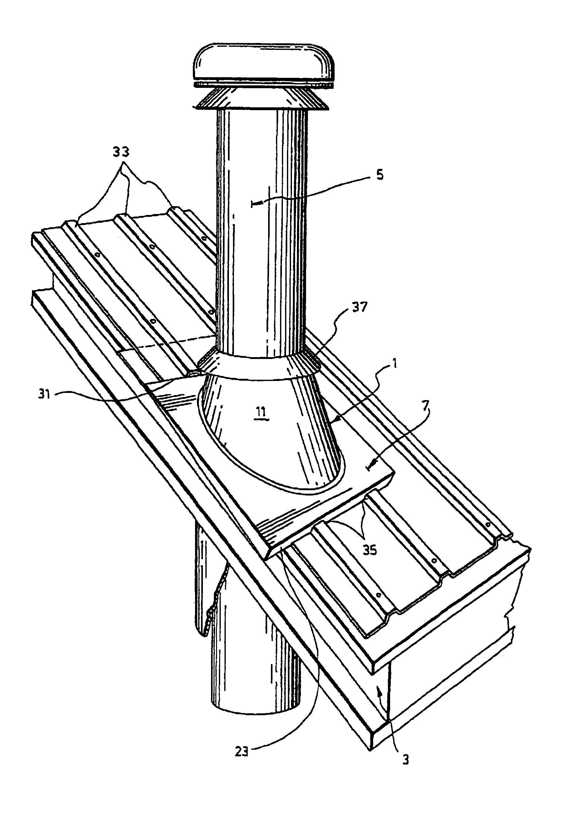
[0044]As aforesaid, the flashing 1 according to the invention is intended to be used for weatherproofing the gaps that exist in-between an inclined roof 3 and a vertical member passing therethrough, such as a chimney 5 as shown in the illustrated embodiment (see FIG. 6) or alternatively a pipe, a venting duct or any other kind of member having to pass through the roof.

[0045]The flashing 1 comprises a base member 7 adapted to be mounted over the aperture 9 made in the inclined roof 3 to allow passage of the chimney 5 (see FIG. 5B). The flashing 1 also comprises a surrounding member 11 extending upwardly from the base member 7 to fit around the chimney 5.

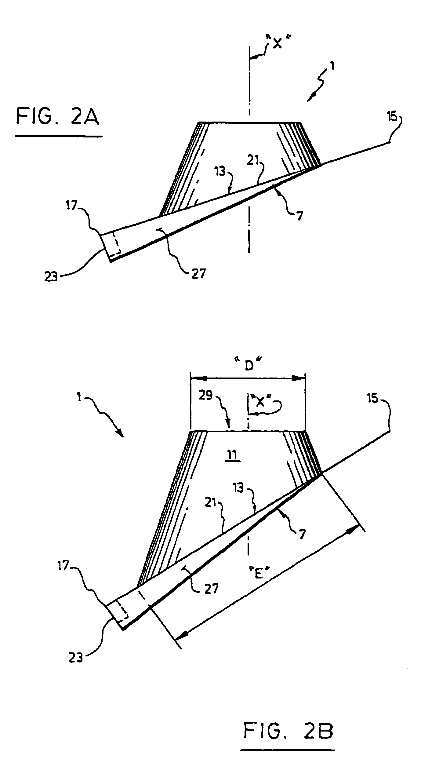
[0046]As better shown in FIGS. 2A, 2B, 3 and 4, the base member 7 is in the form of a hollow housing.

[0047]It comprises a covering panel 13 of quadrilateral shape having a top edge 15 adapted to be positioned on an upper part of the inclined roof, a bottom edge 17 adapted to be positioned on a lower part of the inclined roof and two o...


PUM


Abstract

Disclosed is a flashing for weatherproofing an aperture made in an inclined roof to allow passage of a vertical member such as chimney through the inclined roof. This flashing has a base member adapted to be mounted over the aperture and a surrounding member that is tubular in shape and extends upwardly from the base member to fit around the vertical member. The base member comprises a covering panel of quadrilateral shape having a top edge adapted to be positioned on an upper part of the inclined roof, a bottom edge adapted to be positioned on a lower part of the inclined roof, two opposite side edges and an opening large enough to allow passage of the vertical member therethrough. A bottom side wall projects downwardly from the bottom edge of the covering panel and two lateral side walls respectively extend downwardly from the opposite side edges of the covering panel and sidewardly from the bottom side wall in a tapering fashion. The covering panel, bottom side wall and lateral side walls together defines a hollow housing. This flashing can be installed by (1) cutting a slot in the upper part of the inclined roof above the aperture made therein, so as to receive the top edge of the covering panel of the base member, (2) inserting the top edge of the covering panel into the slot cut in the inclined roof (3) positioning the bottom side wall of the base member onto the lower part of the inclined roof in such a manner that the bottom opening of the surrounding member is located on top of the roof aperture; and (4) fastening the base member to the inclined roof. Thanks to its particular structure and the way it is installed, the flashing according to the invention may be installed in a very easy and efficient manner on any kind of roofs, including inclined roofs with a corrugated structure defining downwardly oriented ridges.

Description

FIELD OF THE INVENTION[0001]The present invention relates to a flashing useful for weatherproofing an aperture made in an inclined roof.[0002]The invention also relates to a method for installing such a flashing onto a roof.BACKGROUND OF THE INVENTION[0003]It is of common practice in the construction industry to use a flashing to seal the interstitial gap between the roof and a vertical member such as a pipe, a venting duct or a chimney passing through an aperture made in this roof.[0004]In addition to ensuring weatherproofing of the roof aperture, the flashing is usually also devised to ensure proper drainage of the water that can accumulate on the roof.[0005]Currently, a variety of roof flashings of different shape are available for weatherproofing an aperture made in a roof to allow passage of a vertical structure. FIGS. 1A to C show three examples of such flashings respectively called “flat flashing”, “gable flashing” and “pitched flashing”.[0006]The flat flashing shown in FIG. ...

Claims


Application Information

Patent Timeline
Patent Type & Authority Patents(United States)
IPC IPC(8): E04D13/14E04B7/00E04D1/36F16K15/03F16L55/07E04D13/00E04D13/147F16L55/00
CPCE04D13/1476
Inventor BIBAUD, ANDREGROULX, SIMON
Owner I C C CIE DE CHEMINEES INDS
Why Eureka
Try Eureka