Casting ring

a technology of casting ring and base, which is applied in the field of mold formation, can solve the problems that the previously known ring and base are not satisfactory in all instances, and achieve the effect of hardening

Inactive Publication Date: 2006-10-03
ASAP
View PDF36 Cites 57 Cited by
  • Summary
  • Abstract
  • Description
  • Claims
  • Application Information

AI Technical Summary

Problems solved by technology

Although the use of casting rings and bases to form molds is known, it is contemplated that previously known rings and bases are not satisfactory in all instances.

Method used


Image

  • Casting ring
  • Casting ring
  • Casting ring

Examples


Embodiment Construction

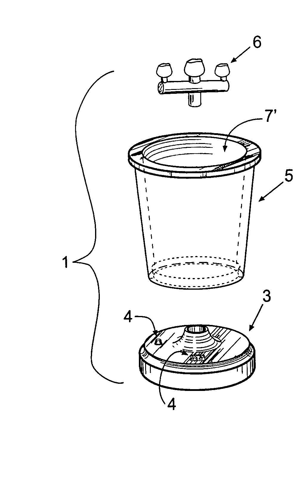
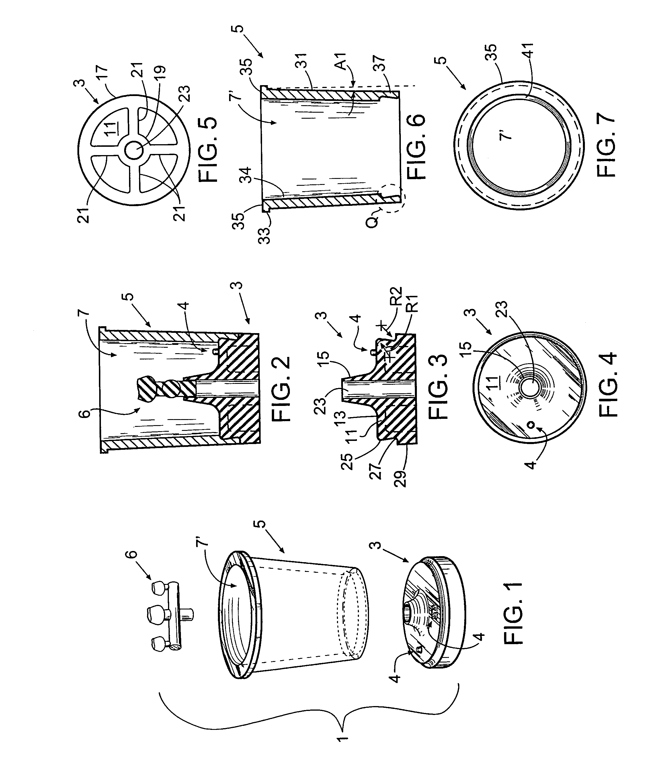
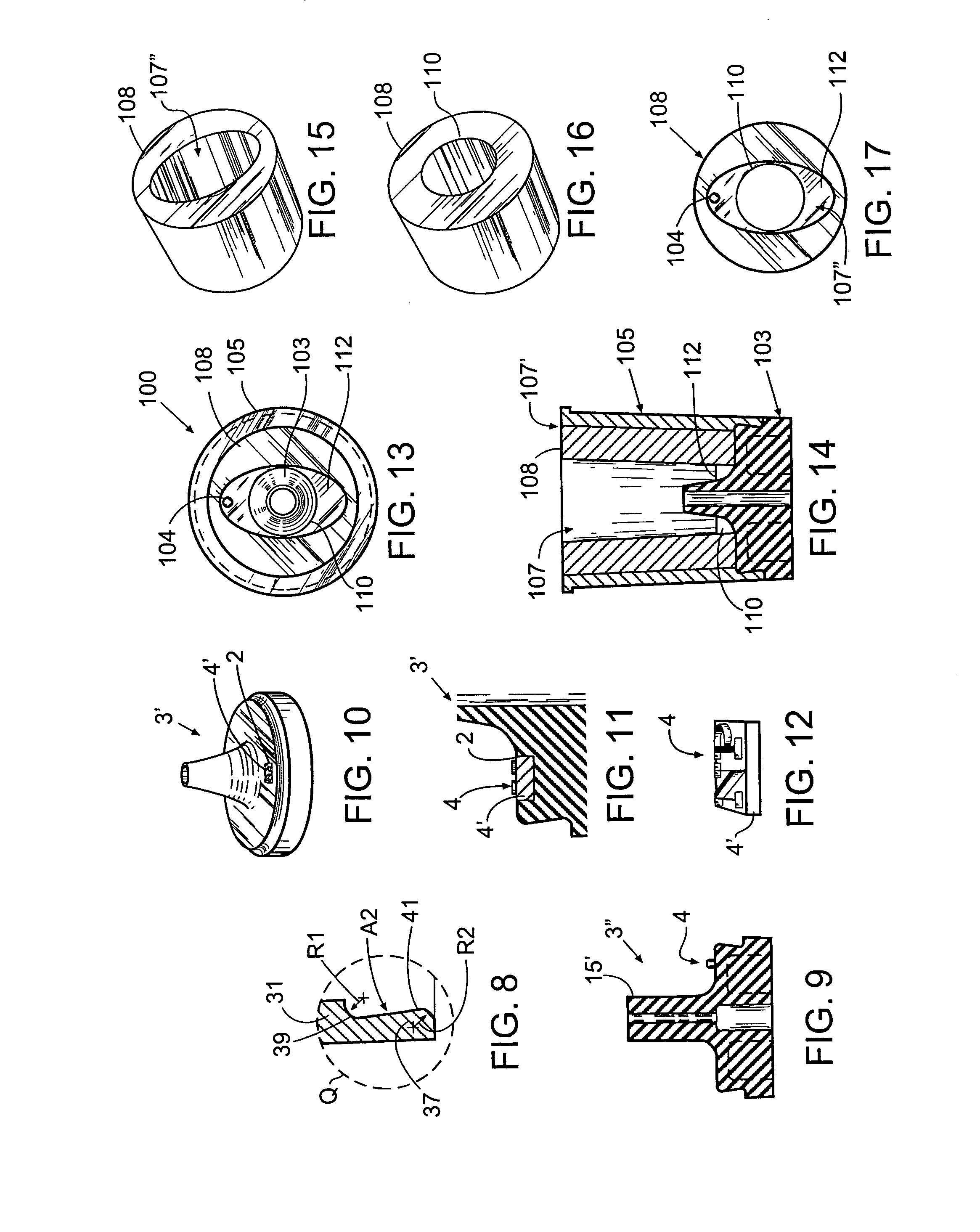
[0029]Reference will now be made to the preferred embodiments of the invention, examples of which are illustrated in the accompanying drawings. While the invention will be described in conjunction with the preferred embodiments, it will be understood that these embodiments are not intended to limit the invention. On the contrary, the invention is intended to cover alternatives, modifications and equivalents, which may be included within the spirit and scope of the invention as defined by the appended claims. In the following detailed description, numerous specific details are set forth in order to provide a thorough understanding of the present invention. However, it will be understood by one of ordinary skill in the art that the present invention may be practiced without these specific details. In other instances, well known methods, procedures, components, and circuits have not been described in detail so as not to unnecessarily obscure the important aspects of the present inventi...


PUM

PropertyMeasurementUnit
angle A1aaaaaaaaaa
angle A1aaaaaaaaaa
melting pointaaaaaaaaaa

Abstract

An apparatus comprising a casting ring and base sized and dimensioned to be coupled together to form a cavity having one or more walls comprising an inner surface of the casting ring, having a bottom comprising an upper surface of the base, and having a form receiving member portion of the base extending into the cavity. This embodiment includes an indicator forming portion sized and positioned to form an indicator on a mold produced by at least partially filling the cavity with investment and allowing the investment to harden. In some instances the casting ring may have a lower segment sized and dimensioned to surround and receive an upper segment of the base to couple the ring and base together, wherein, the casting ring latches onto an outwardly protruding shoulder of the base when the base and casting ring are coupled together.

Description

CROSS-REFERENCES TO RELATED APPLICATIONS[0001]This application claims the benefit of Provisional Application No. 60 / 643,177, filed Jan. 11, 2005.FIELD OF THE INVENTION[0002]The present invention relates generally to mold formation, and more particularly to apparatus used to form molds, particularly molds for forming dental prosthesis.BACKGROUND OF THE INVENTION[0003]In some instances, the formation of a mold used to cast or otherwise form dental prosthesis or other small castings is accomplished using an apparatus comprising a casting ring and a base. Examples of such apparatus as well as descriptions as to how they are used can be found in at least U.S. Pat. Nos. 1,639,411, 5,153,095, 5,406,999, 5,655,692, 5,688,533, and 6,386,503, each of which is herein incorporated by reference in its entirety.[0004]In some instances: (a) a form is positioned on a form receiving portion (typically a sprue former) of the base that extends into a central cavity of the flask formed by the casting r...

Claims


Application Information

Patent Timeline
Patent Type & Authority Patents(United States)
IPC IPC(8): B22C21/00
CPCB22C9/04
Inventor SULLIVAN, MICHAEL R.MEHTA, ASHWIN
Owner ASAP
Why Eureka
Try Eureka