Extendable aluminum bar clamp

a technology of aluminum bar clamps and adjustable bars, which is applied in the field of adjustable bar clamps, can solve the problems of inefficient and expensive shipping of long bar clamps, increased cost of overly long bar clamps, and increased labor costs

Inactive Publication Date: 2006-10-03
HARBOR FREIGHT TOOLS USA
View PDF7 Cites 49 Cited by
  • Summary
  • Abstract
  • Description
  • Claims
  • Application Information

AI Technical Summary

Benefits of technology

[0006]One object of the present invention is to provide a single bar clamp capable of this object is achieved in a typical bar clamp modified to include a two-member bar with one member extending from the other to a selective location where it is releasably secured. In a preferred embodiment, a first member telescopes from the tubular second member. A transverse hole and removable pin is located at the entry of the second member. The first member contains a plurality of transverse holes spaced along its length. The pin can be placed through the transverse hole in the second member

Problems solved by technology

However, overly long bar clamps are more expensive and their use can also be more difficult and/or clumsy than a shorter bar clamp.
Shipping the longer bar clamps is inefficient and expensive because of the increased volume of each clamp, raising shipping costs and resulting in the shipment of fewer pieces in each sh

Method used


Image

  • Extendable aluminum bar clamp
  • Extendable aluminum bar clamp
  • Extendable aluminum bar clamp

Examples


Embodiment Construction

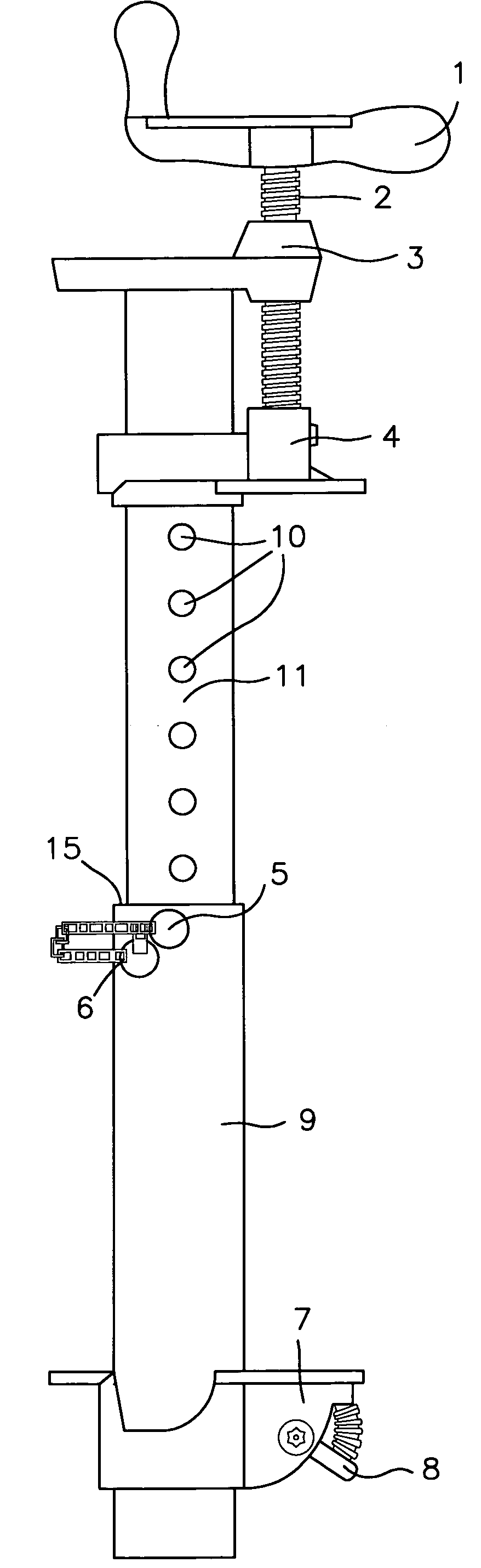
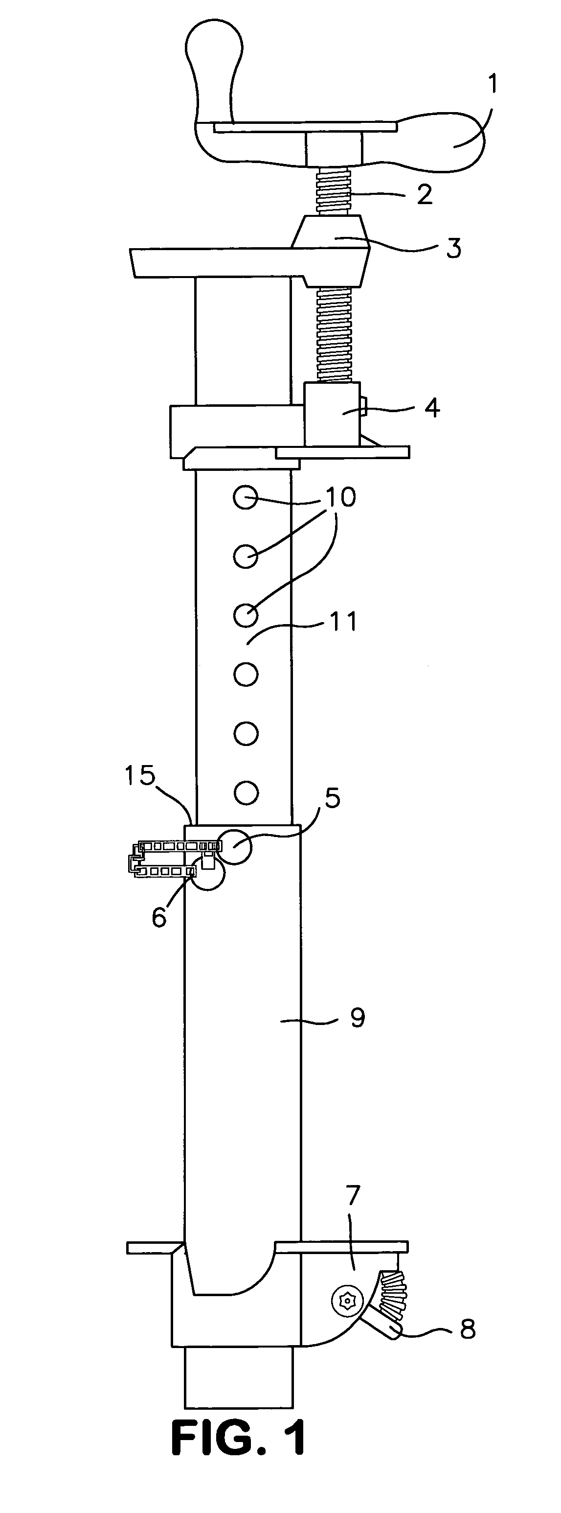
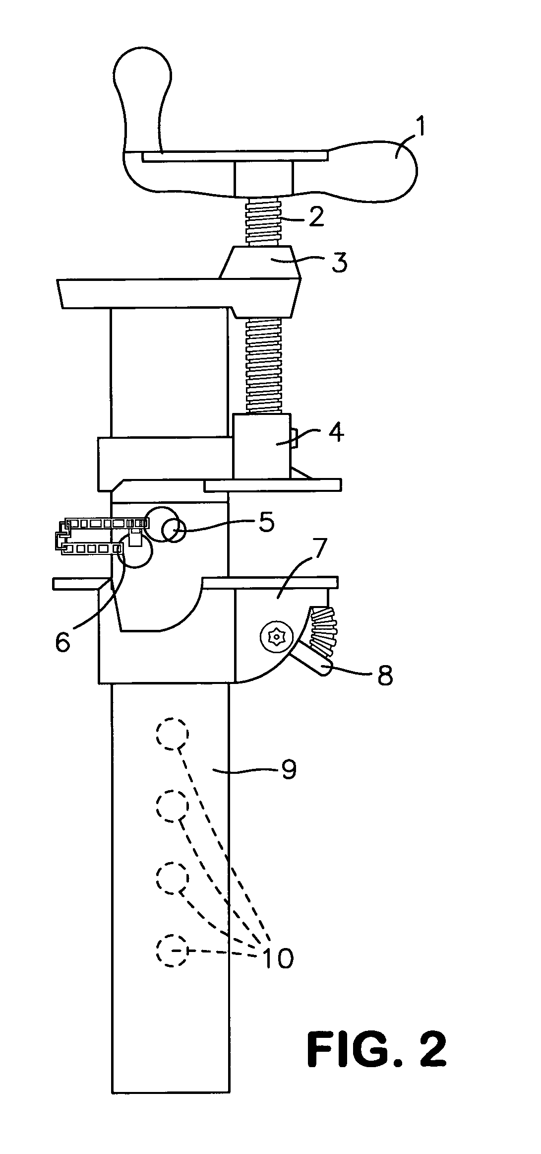
[0012]The adjustable bar clamp of the present invention comprises a bar with inner 11 and outer 9 bar members and a first 4 and second 7 jaw member which are slidably disposed on the bar members. The bar members are tubular, with the inner bar member 11 slidably disposed within the outer bar member 9. In an alternate embodiment, the bar members can be u-shaped, without a full bottom wall portion. The inner bar member 11 has a plurality of spaced transverse holes 10. A locking pin 5 fits through a transverse hole 13 adjacent the entry end 15 to the outer bar member 9 and a transverse hole of the inner bar member 11 to fix the bar members in relation to one another. The locking pin 5 is secured to the outer bar member 9 by a chain 6. The inner and outer bar members 9, 11 are preferably made of metal according to strength considerations.

[0013]In the illustrated embodiments, the inner and outer bar members 9, 11 are rectangular in cross-section, but other cross-sectional configurations ...


PUM


Abstract

A bar clamp including a first bar member and a second bar member with the second bar member telescoping out from the first bar member. A securing mechanism, such as a pin in the first member, releasably secures the members together at a preferred telescoping position. The second bar member has a jaw member that can be advanced or retracted by means of a linear actuator and the first bar member has a jaw member that can be adjusted by positioning the cam-action locking mechanism in one of the notches disposed along the length of the first bar member. As a result of the telescoping relationship of the bar members, workpieces of varying sizes may be clamped between the jaw members without the need of multiple bar clamps of varying lengths.

Description

FIELD OF INVENTION[0001]The present invention relates to clamps generally, and more specifically to adjustable bar clamps capable of applying a clamping force at a plurality of working lengths.BACKGROUND OF THE INVENTION[0002]Bar clamps are well known in many applications, including to the construction industry as well as to craftsmen, for use in holding a work piece in a fixed position. Typically, a bar clamp is used to hold multiple objects together for gluing, welding, or other purposes where it is advantageous to temporarily retain the multiple objects comprising the workpiece in a fixed position.[0003]A bar clamp secures workpieces between the clamp's moveable arms. Different size workpieces can be accommodated by adjusting the clamp's jaw members along the length of the bar. A given bar clamp can accommodate workpieces ranging in size from a very small piece when the jaw members are disposed close together, up to a large piece when the jaw members are at opposite ends of the b...

Claims


Application Information

Patent Timeline
IPC IPC(8): B25B1/02
CPCB25B5/068B25B5/102B25B5/166
Inventor KIRK, BEN
Owner HARBOR FREIGHT TOOLS USA
Why Eureka
Try Eureka