Coating process

Inactive Publication Date: 2006-10-03
HIGHLAND ELECTROPLATERS
View PDF16 Cites 2 Cited by
  • Summary
  • Abstract
  • Description
  • Claims
  • Application Information

AI Technical Summary

Benefits of technology

[0011]The alkaline solution may have a pH>11 and preferably of about 12. The alkalinity of the solution may be achieved by the presence of a suitable material, such as sodium hydroxide. Most preferably, the sodium hydroxide is present in relatively high concentration relative to the zinc and may be present in a range of 3–4M. It has been found that the use of an alkaline process facilitates the formation of a crushable coating.
[0012]Preferably, the component is agitated in the plating solution. Where the component is a screw compressor component, the component may be mounted vertically in the solution and rotated about its axis, the flutes in the component tending to cause the solution to move up and down the flutes relative to the component. Surprisingly, such agitation is far more effective in achieving satisfactory plating using the method of the invention, and the conventional method of agitating the solution while the component remains stationary provides significantly poorer results.
[0013]Preferably, the anode is in the

Problems solved by technology

However, where the thickness of the applied coating is critical, as in a zero tolerance or oil free compressor screw, the resulting differences in coating thickness across an area are likely to be

Method used


Image

  • Coating process
  • Coating process
  • Coating process

Examples


Example

DETAILED DESCRIPTION OF THE DRAWINGS

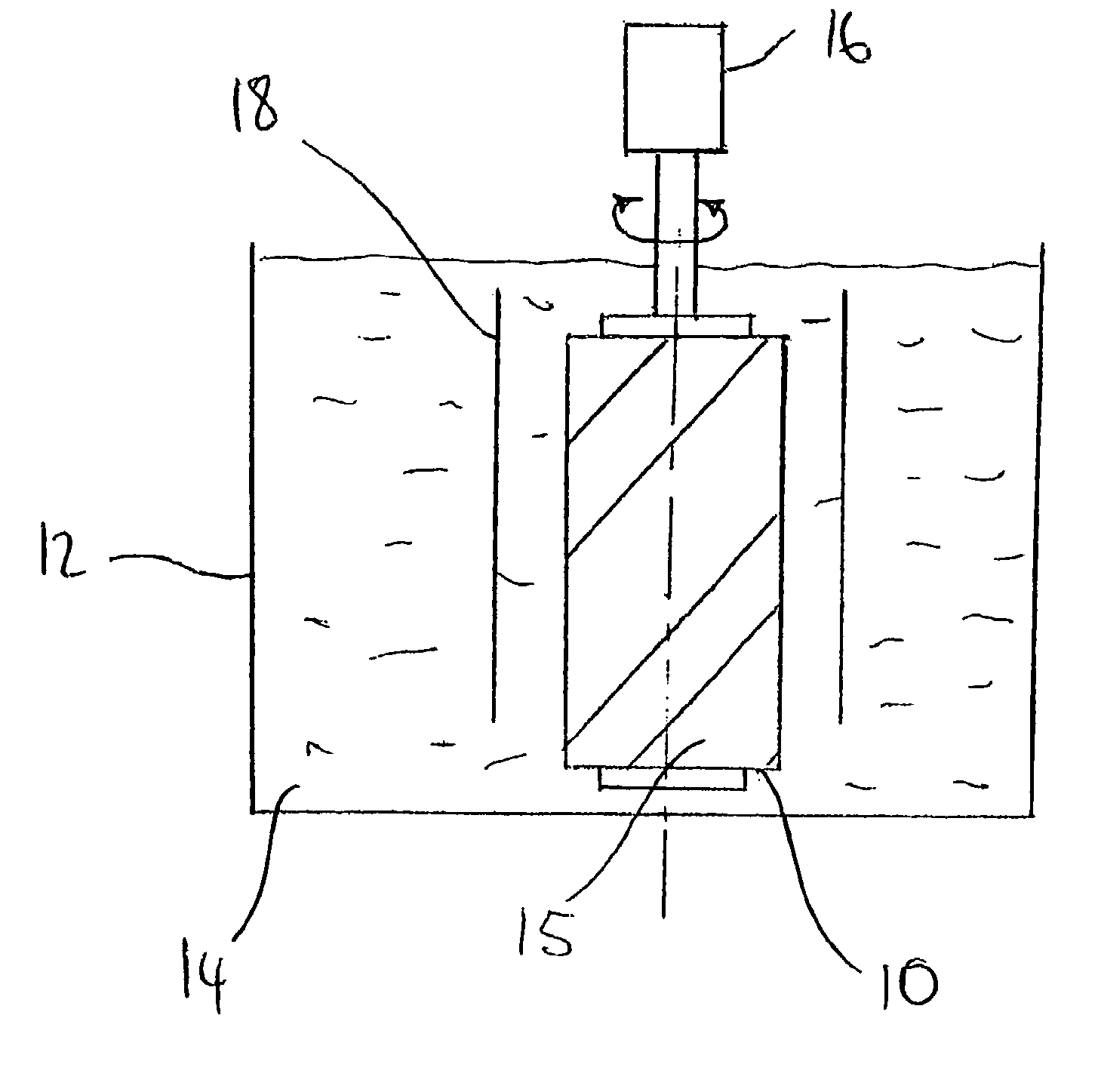
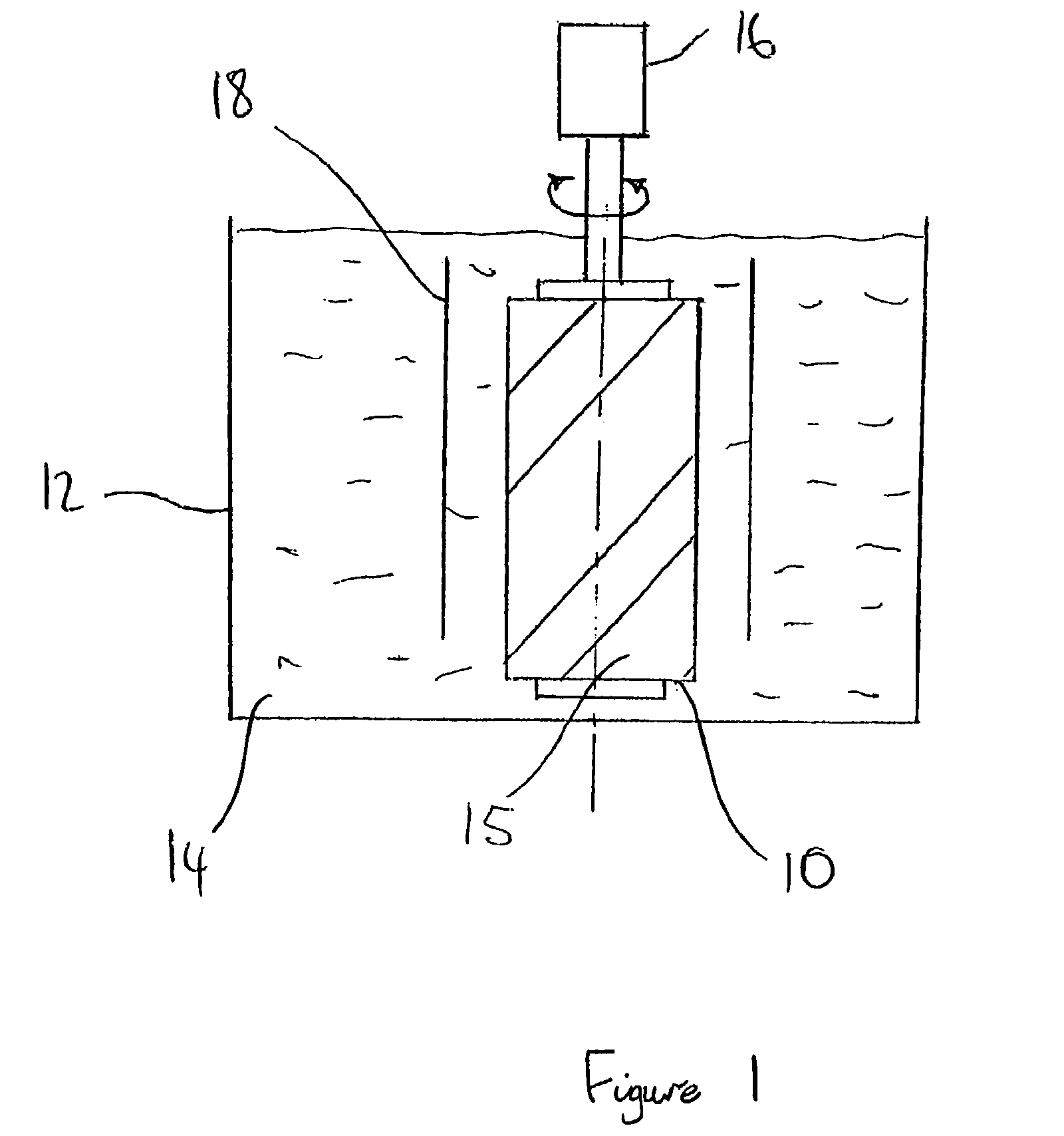
[0019]FIG. 1 illustrates an electroplating process in accordance with a preferred embodiment of the present invention, for use in applying a coating of zinc-nickel alloy to selected areas of a component, in this example a screw 10 of an oil free zero tolerance compressor, such as described in U.S. Pat. No. 6,167,771.

[0020]The screw 10 is suspended in a tank 12 filled with an alkaline zinc-nickel solution 14, as will be described in more detail below. The screw 10 serves as the cathode such that the zinc and nickel are deposited on the screw 10. The alloy is intended to be applied only to selected areas of the screw 10, and the other areas are masked 15, using techniques familiar to those of skill in the art.

[0021]A particular technique to mask part of the screw 10 involves initially applying masking tape to areas which require coating. A lacquer coating, such as VINOMIT (Trade Mark) is then applied to the unmasked areas. Once the lacquer has dried...


PUM

PropertyMeasurementUnit
Molar densityaaaaaaaaaa
Current densityaaaaaaaaaa

Abstract

This invention relates to a process for electroplating a selected surface area of a component with a crushable zinc alloy, the method comprising utilizing a relatively low current density in an alkaline solution during the electroplating process to provide a crushable coating of said zinc alloy on said selected surface area.

Description

FIELD OF THE INVENTION[0001]This invention relates to a coating process, and in particular to an electroplating process for use in applying a zinc alloy coating to a component, and also to components coated in accordance with such a process.BACKGROUND OF THE INVENTION[0002]Recently, there have been significant advances in the design of screw machines, such as described in U.S. Pat. Nos. 5,947,710 and 6,167,711, the disclosures of which are incorporated herein by reference. Based on these and other advances, “zero clearance” compressor screws have been produced, one of the main advantages of such compressors being that the screws may operate effectively and efficiently in the presence of minimal or no sealing and lubricating oil between the screw rotor profiles. However, it has proved difficult to achieve the associated high tolerances in the screw rotor profiles using techniques which are commercially viable.[0003]It is known to coat metal components to provide selected surface char...

Claims


Application Information

Patent Timeline
IPC IPC(8): C25D5/02C25D3/56C25D5/16C25D5/48
CPCC25D3/565C25D5/022C25D5/16C25D5/48C25D5/605
Inventor REED, ALLANBOETTGER, JOHN MATTHEWGAROSSHEN, THOMAS J.
Owner HIGHLAND ELECTROPLATERS
Why Eureka
Try Eureka