Information transmission system and information transmission method, and, optical space transmission system and optical space transmission method

a transmission system and information transmission technology, applied in the field of information transmission system and information transmission method, can solve problems such as circuit disconnection, circuit quality degradation, and difficulty in preparing a large aperture, and achieve the effect of reducing the degradation of transmission quality and circuit disconnection

Inactive Publication Date: 2006-10-03
NTT DOCOMO INC
View PDF29 Cites 11 Cited by
  • Summary
  • Abstract
  • Description
  • Claims
  • Application Information

AI Technical Summary

Benefits of technology

[0021]It is a first object of the present invention to provide an optical space transmission system, an optical space transmission method and an optical space transmission apparatus which can decrease degradation of transmission quality and circuit disconnection even when the refractive index of the air changes due to fluctuations of temperature and humidity of the air.

Problems solved by technology

Thus, there is a problem in that circuit quality degradation or circuit disconnection occurs due to the above-mentioned fluctuations even in good weather.
However, it is difficult to prepare a large aperture due to lack of image formation technique and limitation of the size of the apparatus.
However, for realizing high capacity information transmission by the conventional information transmission system, there is a problem in that keeping reliable availability and long distance transmission are difficult.
This frequency band is resistant to fog, however, very large propagation loss occurs due to rain in this frequency band.
In addition, as for optical space transmission, it is resistant to rain, however, remarkably large propagation loss occurs due to degradation of visibility by fog.
As mentioned above, the conventional information system in which only one of radio transmission and optical space transmission is performed is not resistant to rain or fog.
Thus, it is necessary to provide a margin considering rain or fog so that keeping reliable availability or long distance transmission are difficult.

Method used


Image

  • Information transmission system and information transmission method, and, optical space transmission system and optical space transmission method
  • Information transmission system and information transmission method, and, optical space transmission system and optical space transmission method
  • Information transmission system and information transmission method, and, optical space transmission system and optical space transmission method

Examples


first embodiment

[0129]In the following, the first embodiment which relates to the first object of the present invention will be described with reference to figures. In this embodiment, like reference numerals indicate like elements throughout the several views. In this embodiment, electrical / optical (E / O) converters and optical / electrical (O / E) converters are not shown in the figures.

[0130]FIGS. 3–5 show configurations of the sending station and the receiving station in which a plurality of optical transmitters or a plurality of optical receivers are provided.

[0131]In the following examples, two optical transmitters or two optical receivers are provided for an example of a plurality of optical transmitters or a plurality of optical receivers. However, more optical transmitters or more optical receivers can be provided.

[0132]In FIG. 3, in a sending station 10, an information signal (data input signal) from an input terminal 11 is converted into a radio modulation signal by a radio signal modulation ...

second embodiment

[0189]Next, a second embodiment of the present invention corresponding to the second object will be described with reference to accompanying figures. The second embodiment will be described by using examples from 2-1 to 2-5. Like reference numerals indicate like elements throughout the several views.

[0190]In the second embodiment, the object is achieved by combining optical space transmission in the first embodiment and radio transmission.

[0191](Example 2-1)

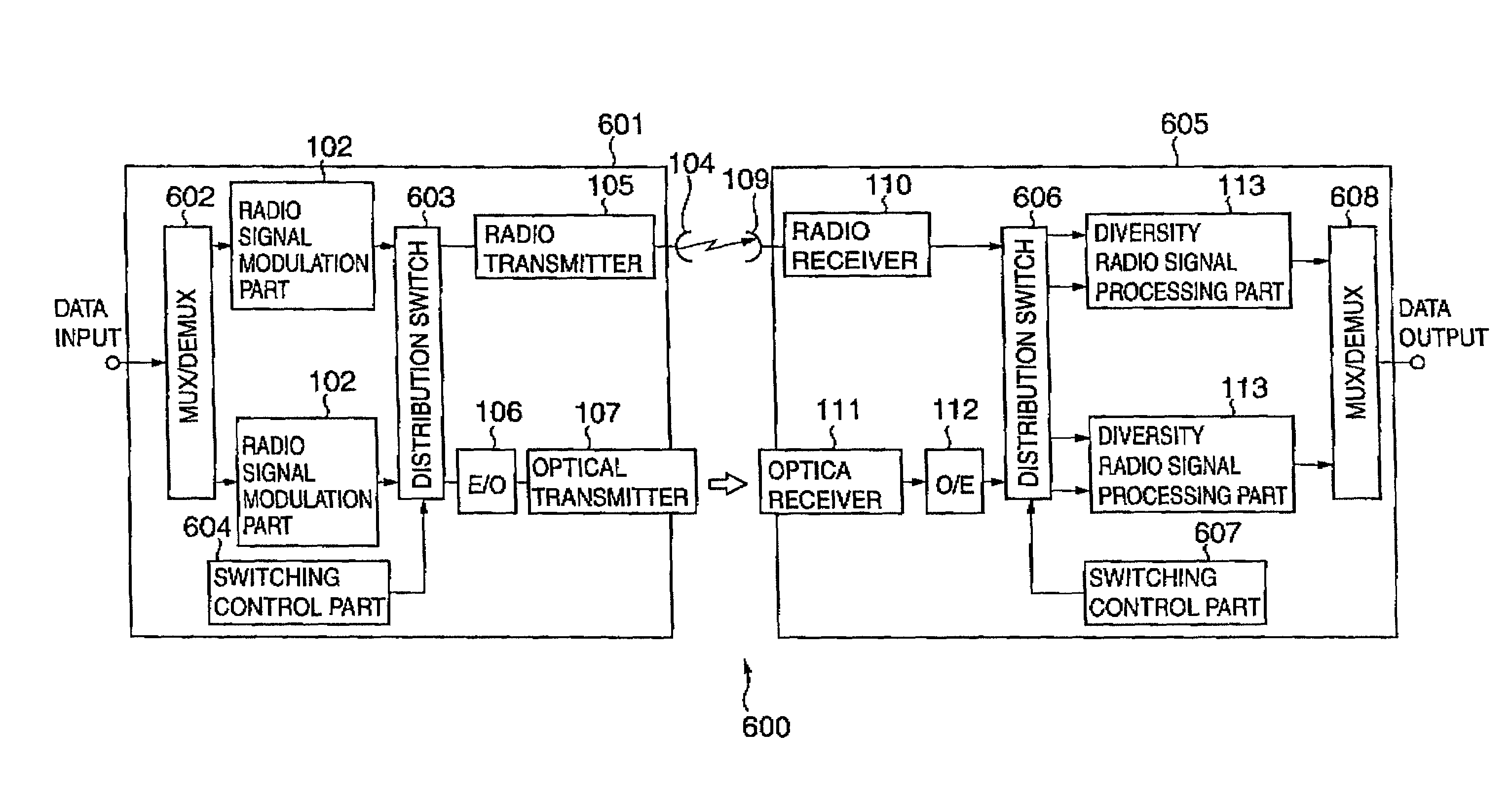
[0192]In the following, a configuration and an operation of an information transmission system of the present invention will be described with reference to FIG. 19.

[0193]First, a configuration of an information transmission system of this example will be described. A sending station 101 includes a radio signal modulation part 102 which converts input data (information signal) into a radio modulation signal of radio frequency band, a divider 103 which divides a radio modulation signal into two routes, a radio transmitter 105 which...

example 2-2

(Example 2-2)

[0202]Next, an information transmission system of an example 2-2 of the present invention will be described with reference to FIG. 20. FIG. 20 is a block diagram of the information transmission system of the example 2-2 of the present invention.

[0203]This example is the same as the example 2-1 basically. However, in this example, the sending station converts input data (information signal) to a radio modulation signal of intermediate frequency band. In FIG. 20, the same numbers are assigned to the same components as those of the example 2-1.

[0204]In a sending station 201 in an information transmission system 200 of this example, an radio signal modulation part 202 converts input data (information signal) into a radio modulation signal of intermediate frequency band. A frequency converter 203 converts frequency of the radio modulation signal from the intermediate frequency band to radio frequency band.

[0205]In a receiving station 204, a frequency converter 205 converts f...


PUM


Abstract

An information transmission system for transmitting information from a sending apparatus to a receiving apparatus is provided. The information transmission system includes: a sending apparatus for modulating an information signal, generating a plurality of signals including an optical signal from the information signal which is modulated, and transmitting the plurality of signals via a plurality of routes; and a receiving apparatus for receiving the plurality of signals from the sending apparatus, diversity-combining the plurality of signals, and outputting the information signal, in which the plurality of signals are a plurality of optical signals or signals including a radio signal.

Description

BACKGROUND OF THE INVENTION[0001]1. Field of the Invention[0002]The present invention relates to an information transmission method and the system. More particularly, the present invention relates to an information transmission method and the system tolerant of both of rain and fog. In addition, the present invention relates to an optical space transmission system and the method in which degradation of transmission quality and circuit disconnection are decreased.[0003]2. Description of the Related Art[0004]First, conventional technologies of a first aspect will be described.[0005]FIGS. 1A and 1B show block diagrams showing conventional optical space transmission apparatuses.[0006]As for FIG. 1A, in a sending station 1, a signal to be transmitted is input from an input terminal 3. Then, the signal is converted to a signal format for optical transmission by a signal converter 5. The optical transmitter 6 sends the optical signal to the air. The optical signal is received by an optical...

Claims


Application Information

Patent Timeline
Patent Type & Authority Patents(United States)
IPC IPC(8): H04B10/00H04B10/11H04B7/02H04B7/06H04B7/08H04B10/112H04L1/22
CPCH04B10/032H04B10/11
Inventor ABURAKAWA, YUJIYOSHINO, HITOSHIOTSU, TORUYAMAO, YASUSHI
Owner NTT DOCOMO INC
Why Eureka
Try Eureka