Apparatus and method for electronic device control

a technology of electronic devices and apparatus, applied in static indicating devices, instruments, substation equipment, etc., can solve the problems of reducing the convenience and portability of mobile communication devices, limiting the inputs of multiple applications, and extra external devices

Inactive Publication Date: 2006-10-03
GOOGLE TECH HLDG LLC
View PDF7 Cites 101 Cited by
  • Summary
  • Abstract
  • Description
  • Claims
  • Application Information

AI Technical Summary

Problems solved by technology

Unfortunately, extra external devices reduce the convenience and portability of a mobile communication device.
Unfortunately, the small size of some electronic devices limits the available inputs for multiple applications.
As mentioned, the controls for a game on a mobile communication device are limited to the limited number of existing inputs such as keys and buttons.
These inputs are not placed in optimal positions for efficient gaming or navigation control.
Furthermore, to conserve space, these inputs are small and congested due to the small size of many electronic devices.
Thus, optimal use of the inputs is difficult due to their size and location.
Unfortunately, it is impossible to configure existing gaming system games for compact portable electronic devices because of the specific input requirements.
For example, many existing gaming systems use joysticks that cannot be incorporated into mobile communication devices without sacrificing size and aesthetics.
As another example, it is uncomfortable to play games that require the use of navigation and action inputs on mobile phones because these games require the use of two hands to play the games.
The existing small mobile phone keypad is uncomfortable and non-intuitive for such games.

Method used


Image

  • Apparatus and method for electronic device control
  • Apparatus and method for electronic device control
  • Apparatus and method for electronic device control

Examples


first embodiment

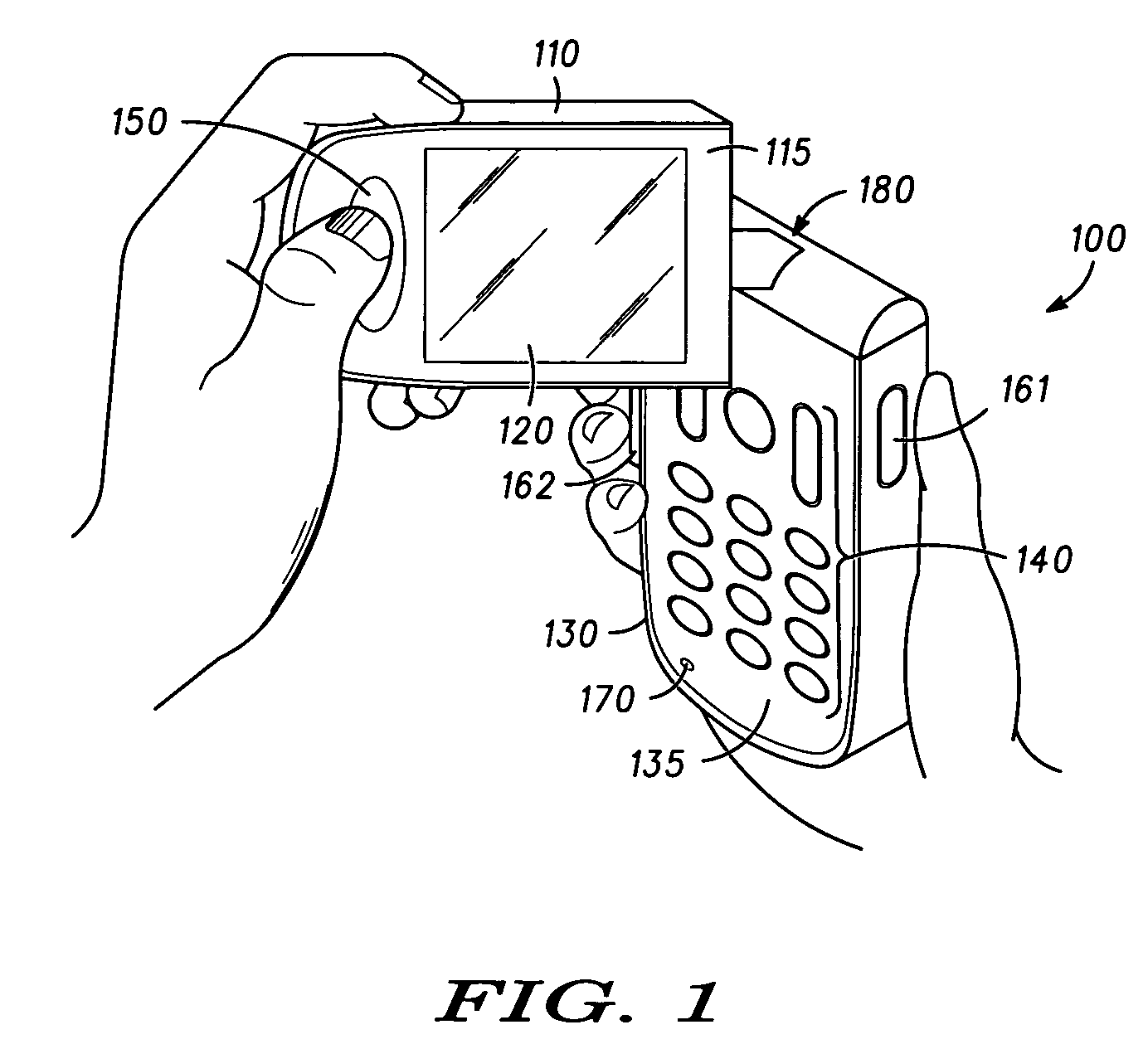
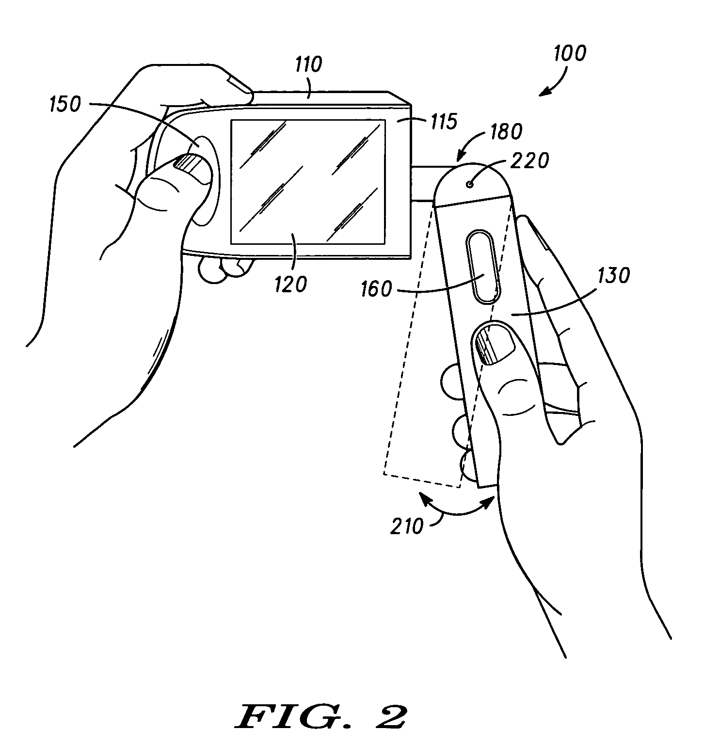
[0031]FIG. 1 is an exemplary illustration of an electronic device 100 according to a The electronic device 100 may be a mobile communication device, an electronic gaming device, a personal digital assistant, or any other electronic device. The electronic device 100 can include a display housing 110 having a display housing face 115, a display 120 on the display housing face 115, and a main housing 130 having a main housing face 135. The display housing 110 can be coupled to the main housing 130 at a pivot point 180. For example, the display housing 110 can be pivotably attached to the main housing 130 using a shaft and hinge, using a ball and socket, or using any other connection for pivotal attachment. Thus, the display housing 110 can rotate about at least two axes of rotation with respect to the main housing 130.

[0032]The pivot point 180 can include internal sensors for detecting movement of the display housing 110 relative to the main housing 130. For example, the pivot point 1...

second embodiment

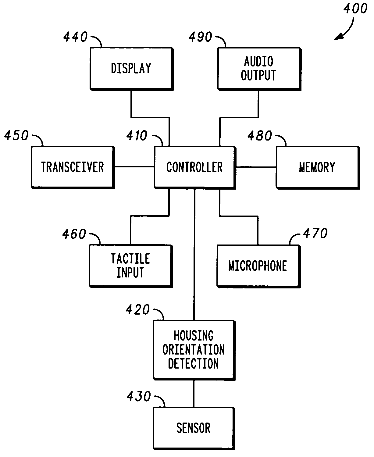
[0038]FIG. 4 is an exemplary block diagram of an electronic device 400 according to a The electronic device 400 can include a controller 410, a housing orientation detection module 420, and at least one sensor 430. The electronic device 400 may also include a display 440, a transceiver 450, a tactile input 460, a microphone 470, a memory 480, and an audio output 490. The transceiver 450 may be a transmitter and / or a receiver. Also, the transceiver 450 may reside in the main housing 130. The tactile input 460 may include a telecommunications input, a keypad, buttons, pressure sensors, dials, or any other tactile inputs. The display 440 may be a liquid crystal display, a light emitting diode display, a plasma display, or any other display useful for displaying visual information. The audio output 490 may be a speaker, a transducer, or any other device useful for providing audio output. The memory 480 may be a random access memory, a read only memory, an optical memory, a magnetic mem...

third embodiment

[0045]FIG. 5 is an exemplary illustration of a electronic device 500 according to a The electronic device 500 may be a mobile communication device, a personal digital assistant, or any other portable electronic device. The electronic device 500 can include a display housing 510, a display housing face 515, a display 520, a main housing 530, a main housing face 535, a tactile input 540 such as a keypad or buttons, a shaft 580, a first sensor 585 such as a shaft encoder, a hinge connection 590, and a second sensor such as a shaft encoder 595. The display housing 510 is coupled to the shaft 580 and the first sensor 585. Thus, the first sensor 585 can detect rotation of the display housing 510 along a first axis of rotation. The main housing 530 is coupled to the second sensor 595 and the hinge 590. Thus, the second sensor 595 can detect rotation of the base housing 530 along a second axis of rotation. Therefore, the first sensor 585 and the second sensor 595 can detect movement of the...


PUM


Abstract

An apparatus and method for electronic device control. The apparatus can include a first housing including a first housing face, a display coupled to the first housing face, a second housing pivotably attached to the first housing the second housing including a second housing face, the second housing face being configured to cover at least a portion of the first housing face. The apparatus can also include a housing orientation detection module coupled to the second housing, the housing orientation detection module configured to detect a position of the second housing relative to the first housing. The apparatus can additionally include a controller configured to display motion on the display based on the position detected by the housing orientation detection module. The second housing can be pivotably attached to the first housing along at least two axes of rotation.

Description

CROSS-REFERENCE TO RELATED APPLICATIONS[0001]This application is related to an application 10 / 326,516 entitled “Apparatus and Method for Application Control in an Electronic Device,” which is hereby incorporated by reference, filed on even date herewith, and commonly assigned to the assignee of the present application.BACKGROUND OF THE INVENTION[0002]1. Field of Invention[0003]The present invention is directed to a method and apparatus for electronic device control. In particular, the present invention is directed to input-devices for movement control in an electronic device.[0004]2. Description of Related Art[0005]Presently, many different applications are being incorporated into small electronic devices. For example, mobile communication devices are incorporating gaming applications and personal digital assistants are incorporating communication applications. When a mobile communication device employs a gaming application, the game must use the existing input devices on the mobile...

Claims


Application Information

Patent Timeline
Patent Type & Authority Patents(United States)
IPC IPC(8): H04Q7/32H04M1/02H04M1/72427
CPCH04M1/0212H04M1/0241H04M1/0243H04M1/72544H04M1/72427H04B1/38
Inventor WONG, DANIELKINERK, KEITH
Owner GOOGLE TECH HLDG LLC
Why Eureka
Try Eureka