Adaptive antenna base station apparatus

a base station and antenna technology, applied in the field of base station apparatus, can solve the problems of increasing the scale of the apparatus, affecting the reception quality, and increasing the computation amount of the conventional adaptive antenna base station apparatus, so as to suppress the interference of other path components, reduce computation and apparatus scale, and suppress correlation components

Active Publication Date: 2006-10-03
PANASONIC CORP
View PDF16 Cites 20 Cited by
  • Summary
  • Abstract
  • Description
  • Claims
  • Application Information

AI Technical Summary

Benefits of technology

[0024]In any of the apparatuses of the first aspect and the first to fourth modes of the first aspect of the invention, the adaptive antenna base station apparatus may further comprise a transmission beamforming section for generating a transmission beamweight which determines a directivity of the array antenna by using an output of the direction-of-arrival estimating section and multiplying a transmission signal by the transmission beamweight; N spreading sections for multiplying an output signal of the transmission beamforming section by spread codes corresponding to the antenna elements; and N transmission sections for transmitting output signals of the spreading sections from the array antenna. This structure has an effect of suppressing interference to other path components by transmitting electric waves by directing the directivity of the array antenna common to M paths in the direction that maximizes the combined power of M path components coming from the nearby directions, and reducing the amount of computation and the apparatus scale by transmitting electric waves by directing the directivity of the array antenna to the direction of arrival of a maximum of M path components estimated from a single angular spectrum, with respect to the M path components whose directions differ from one another in a wide range.
[0025]An adaptive antenna base station apparatus according to the second aspect of the invention comprises an array antenna including N (N being a natural number) antenna elements; Nu×N reception sections for respectively performing orthogonal detection of code-multiplexed high-frequency signals, respectively received by the antenna elements of the array antenna, after frequency conversion of the code-multiplexed high-frequency signals in association with Nu (Nu being a natural number) pieces of user-by-user information included in a received wave; Nu×N×M despreading sections for performing despreading operations, corresponding to delay times of M (M being a natural number) path components included in output signals of the reception sections, with respect to the output signals of the reception, sections; Nu×M correlation computing sections for performing correlations among the antenna elements on output signals of the despreading sections for each path; Nu correlation combining sections for combining output signals of the correlation computing sections; an interuser correlation combining section for combining Nu output signals of the correlation combining sections; Uu other-user correlation subtracting sections for computing correlation components of (Nu−1) other users by subtracting an output of that correlation combining section which is associated with a target user from an output of the interuser correlation combining section; and Nu direction-of-arrival estimating sections for estimating a direction of arrival of the target user by using outputs of the other-user correlation subtracting sections. This structure has effects of suppressing correlation components originating from incoming electric waves from another user and accurately detecting the direction of arrival of electric waves from a predetermined user.
[0026]According to the first mode of the second aspect of the invention, the adaptive antenna base station apparatus may further comprise Nu×M beamforming sections for generating beamweights that minimize reception power of other user components, which become interference waves for every Nu users, from output signals of the Nu direction-of-arrival estimating sections and output signals of the Nu other-user correlation subtracting sections, multiplying the beamweights by output signals of M×N spreading sections and combining M paths for every Nu users; Nu Rake combining sections for combining outputs of the beamforming sections; and Nu data determining sections for outputting received data from outputs of the Rake combining sections in accordance with code determination. This structure brings about an effect of adaptively suppressing the interference.
[0027]In the apparatus of the second aspect of the invention or the apparatus of the first mode of the second aspect of the invention, the adaptive antenna base station apparatus may further comprise an all user directions combining section for combining steering vectors of the array antenna from output signals of the Nu direction-of-arrival estimating sections; Nu transmission beamforming sections for generating transmission beamweights which minimize transmission power to other users from an estimated value of the direction of arrival and an output signal of the all user directions combining section for every Nu users and multiplying a transmission signal by the transmission beamweights; Nu×N spreading sections for multiplying output signals of the transmission beamforming sections by spread codes corresponding to the Nu users and N antenna elements; and Nu×N transmission sections for transmitting output signals of the spreading sections from the array antenna. This structure has an effect of improving the SIR by electric waves by directing the directivity of the array antenna common to M paths in the direction that maximizes the combined power of M path components coming from the nearby directions and forming a null with the directivity of the array antenna with respect to other users who are communicating at the same time.
[0028]In the apparatus of the second mode of the second aspect of the invention, the all user directions combining section may combine the steering vectors in a direction of estimation of the array antenna by a weight coefficient which depends on the transmission power. This structure has an effect of forming the optimal transmission beam by forming a null which depends on the transmission power of each user.
[0029]In any of the apparatuses of the second aspect of the invention and the first to third modes of the second aspect of the invention, the interuser correlation combining section may combine outputs of the correlation combining sections of a user which are signals of a fast data rate. This structure has effects of suppressing correlation components originating from high-transmission-power electric signal waves incoming at a fast data rate and accurately detecting the direction of arrival of electric waves from a predetermined user.

Problems solved by technology

As a signal which is received by a base station apparatus is interfered by various signals, its reception quality is deteriorated.
However, the conventional adaptive antenna base station apparatus with the above-described structure acquires the angular spectrum path by path and requires, for the respective paths, the DOA estimating sections which perform the same operation., This disadvantageously increases the scale of the apparatus.
This raises another problem that the amount of computation which should be done by the conventional adaptive antenna base station apparatus increases exponentially in accordance with an increase in the number of the antenna elements and an increase in the number of the paths to be subjected to Rake combining.

Method used


Image

  • Adaptive antenna base station apparatus
  • Adaptive antenna base station apparatus
  • Adaptive antenna base station apparatus

Examples


first embodiment

(First Embodiment)

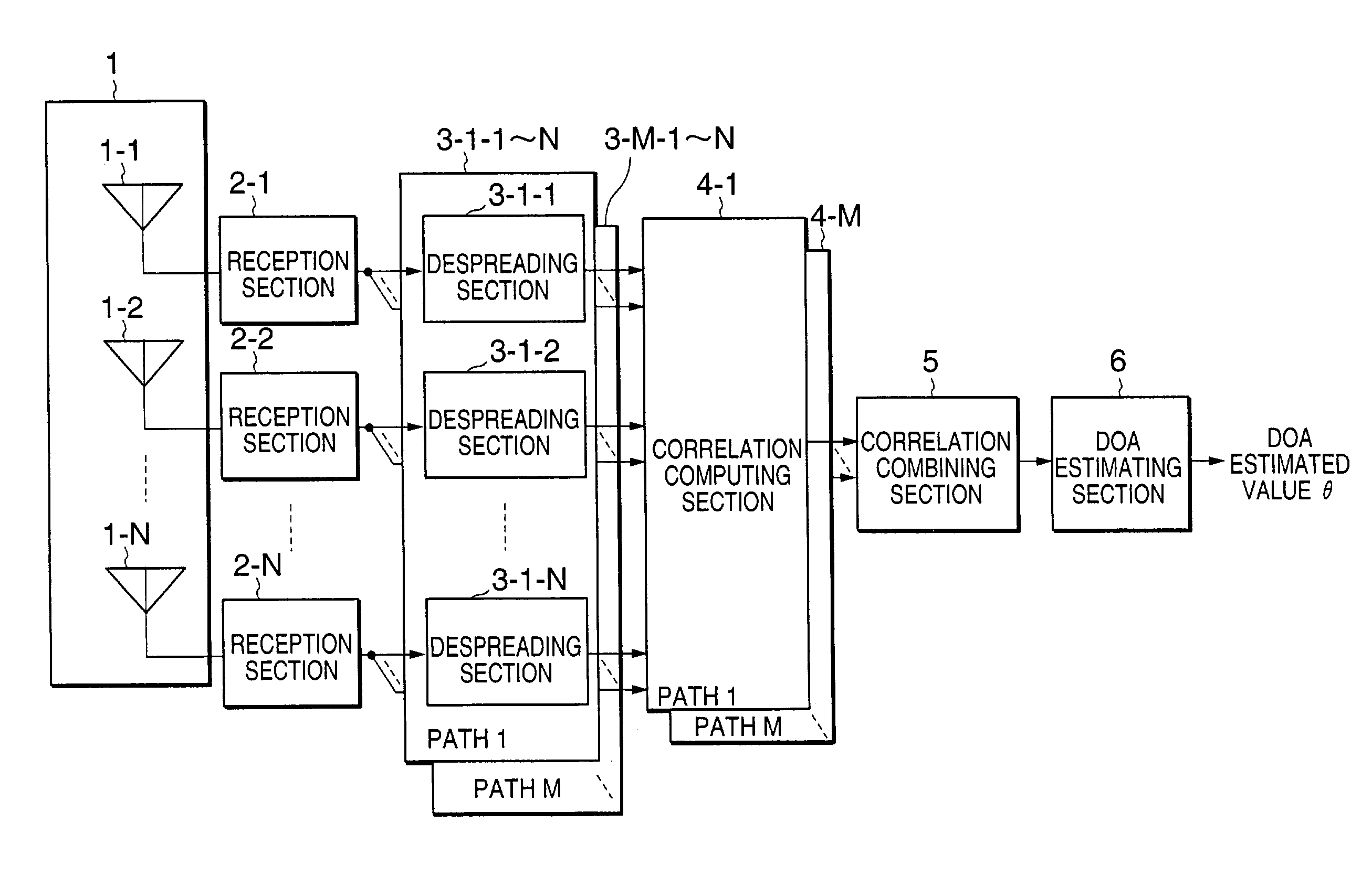
[0039]FIG. 1 is a block diagram showing the structure of an adaptive antenna base station apparatus according to the first embodiment of the invention, which comprises an array antenna 1, reception sections 2-1 to 2-N, despreading sections 3-1-1 to 3-1-N, . . . , and 3-M-1 to 3-M-N, correlation computing sections 4-1 to 4-M, a correlation combining section 5 and a DOA (Direction-Of-Arrival) estimating section 6. Those components will be discussed in detail.

[0040]The array antenna 1 receives code-multiplexed high-frequency signals at the N antenna elements 1-1 to 1-N, inputs the signals to the reception sections 2-1 to 2-N respectively provided in the antenna elements 1-1 to 1-N, performs high-frequency amplification, frequency conversion, orthogonal detection and A / D conversion in order and inputs the resultant signals to the despreading sections 3-1-1 to 3-1-N, . . . , and 3-M-1 to 3-M-N.

[0041]The despreading sections 3-1-1 to 3-1-N, . . . , and 3-M-1 to 3-M-N per...

second embodiment

(Second Embodiment)

[0054]FIG. 3 is a block diagram showing the structure of an adaptive antenna base station apparatus that forms a reception directive beam based on the result of estimation done in a DOA estimating section 6 according to the second embodiment of the invention. The apparatus comprises an array antenna 1, reception sections 2-1 to 2-N, despreading sections 3-1-1 to 3-1-N, . . . , and 3-M-1 to 3-M-N, correlation computing sections 4-1 to 4-M, a correlation combining section 5, a DOA estimating section 6, beamforming sections 7-1 to 7-M, a Rake combining section 8 and a data determining section 9. The following will mainly discuss what differs from the first embodiment.

[0055]The operation up to the acquisition of a DOA estimated value by the DOA estimating section 6 based on the signals received by the array antenna 1 is similar to that of the first embodiment. In the second embodiment, however, the DOA estimating section 6 detects only the direction that shows the hig...

third embodiment

(Third Embodiment)

[0064]FIG. 4 is a block diagram showing the structure of an adaptive antenna base station apparatus that adaptively forms a transmission directivity based on the result of estimation done in the DOA estimating section 6 of the first embodiment. The apparatus comprises an array antenna 1, reception sections 2-1 to 2-N, despreading sections 3-1-1 to 3-1-N, . . . , and 3-M-1 to 3-M-N, correlation computing sections 4-1 to 4-M, a correlation combining section 5, a DOA estimating section 6, beamforming sections 7-1 to 7-M, a modulating section 20, a transmission beamforming section 21, spreading sections 22-1 to 22-N and transmission sections 23-1 to 23-N. The following will mainly discuss what differs from the first embodiment.

[0065]The operation up to the acquisition of a DOA estimated value by the DOA estimating section 6 based on the signals received by the array antenna 1 is similar to that of the first embodiment.

[0066]The modulating section 20 modulates transmiss...


PUM


Abstract

An adaptive antenna base station apparatus comprises an array antenna including N (N being a natural number) antenna elements; N reception sections for respectively performing orthogonal detection of high-frequency signals, respectively received by the antenna elements, after frequency conversion; N×M despreading sections for performing despreading operations, corresponding to delay times of M (M being a natural number) path components included in output signals of the reception sections; M correlation computing sections for performing correlations among the antenna elements for each path; a correlation combining section for combining output signals of the correlation computing sections; and a DOA estimating section for estimating a direction of arrival (DOA) by using an output of the correlation combining section. This can ensure collective estimation of DOAs of M path components, thereby reducing the amount of computation of estimating the DOAs for plural paths and the cost for the apparatus.

Description

TECHNICAL FIELD[0001]The present invention relates to a base station apparatus of a CDMA (Code Division Multiple Access) mobile communication type which is equipped with an adaptive antenna which varies the directivity of its array antenna based on the result of directional estimation using the array antenna.BACKGROUND OF THE INVENTION[0002]As a signal which is received by a base station apparatus is interfered by various signals, its reception quality is deteriorated. An array antenna is known as the technology that suppresses this interference and intensely receives electric waves to be received which come only from the direction of arrival. The array antenna can intensely receive electric waves to be received which come only from the direction of arrival by adjusting the amplitudes and phases which are to be given to reception signals by adjusting the weight coefficient (hereinafter called “weight”) by which the reception signals are to be multiplied.[0003]Further, there is Rake ...

Claims


Application Information

Patent Timeline
Patent Type & Authority Patents(United States)
IPC IPC(8): H04M1/00G01S5/02H03K9/00H01Q3/26H04B1/707H04B1/712H04B7/06H04B7/08H04B7/10H04B7/26H04J99/00H04W16/28H04W88/08
CPCH04B7/086H04B1/712H04B7/0617
Inventor KISIGAMI, TAKAAKIFUKAGAWA, TAKASHIYUDA, YASUAKIHOSHINO, MASAYUKI
Owner PANASONIC CORP
Why Eureka
Try Eureka