Controller for internal combustion engine

a controller and internal combustion engine technology, applied in the direction of electrical control, instruments, calibration apparatus, etc., can solve the problems of deteriorating sensor accuracy of ignition timing tburn, affecting the accuracy of motoring waveform estimation, and heavy calculation load

Active Publication Date: 2006-10-03
DENSO CORP
View PDF9 Cites 24 Cited by
  • Summary
  • Abstract
  • Description
  • Claims
  • Application Information

AI Technical Summary

Benefits of technology

[0012]The present invention has been made on the basis of the above-described circumstances. The first object of the invention is to estimate a motoring waveform in an actual operating state with high accuracy irrespective of the operating state of an internal combustion engine or variations in the engines and to sense an ignition timing in a short time with high accuracy by reducing a calculation load for estimating the motoring waveform. The second object of the invention is to sense a correct compression top dead center (TDC) without the effect of noises at the time of correcting the angle error of a crank angle sensor by a cylinder pressure in the internal combustion engine sensed by a cylinder pressure sensor.
[0020]According to the above-described construction, such a cylinder pressure at least from a compression stroke to an expansion stroke that is sensed by the cylinder pressure sensor and the cylinder volume corresponding to a crank angle at least from a compression stroke to an expansion stroke that is sensed by the crank angle sensor are converted to the logarithmic value log P and the logarithmic value log V by the conversion map P and the conversion map V, respectively, and then by reading the logarithmic value log P and the logarithmic value log V in the logarithm map, a change in the cylinder pressure at least from a compression stroke to an expansion stroke can be displayed as the logarithmically converted cylinder pressure waveform on the logarithm map. Thus, it is possible to estimate the motoring waveform by the logarithmically converted cylinder pressure waveform without using a polytropic equation requiring an exponential computation and hence to reduce a computation load.
[0021]Further, according to the present invention, a conventional method of searching a map for a polytropic exponent n according to the operating state of the internal combustion engine, or variations in the internal combustion engines is not employed, but the logarithmically converted cylinder pressure waveform is found for each combustion cycle of the internal combustion engine and the motoring waveform is estimated from the found cylinder pressure waveform. Hence, the motoring waveform is not affected by a change in the operating state of the internal combustion engine, in particular, a change in the variations in the internal combustion engines. As a result, it is possible to estimate the motoring waveform for each combustion cycle with high accuracy and hence to improve the sensing accuracy of the ignition timing.
[0024]According to the above-described construction, a base angle is set at which a change in the cylinder pressure to the crank angle becomes large as compared with a change in the vicinity of the TDC and the cylinder pressure is sensed at the base angle. Hence, noises are less likely to cause errors in the sensing value of the cylinder pressure sensor. Therefore, it is possible to sense a correct TDC (compression top dead center).

Problems solved by technology

However, there is presented a problem that when a position where the crank angle sensor is mounted or variations in the engines cause an error in the value sensed by the crank angle sensor (crank angle), as shown in FIG. 22, the sensing accuracy of the ignition timing Tburn deteriorates.
However, the method of sensing an ignition timing disclosed in JP-2001-55955 A presents the following problem.
That is, when a polytropic exponent “n” is found from a map, a change in the operating state of the internal combustion engine, in particular, variations in the internal combustion engines cannot be sufficiently corrected and hence the motoring waveform cannot be correctly estimated (calculated) to cause a sensing error in the ignition timing.
Moreover, because the exponent of the polytropic equation needs to be calculated, a calculation load is made heavy.
Hence, it is difficult for an ECU (electronic control unit) mounted on an actual vehicle to calculate the exponent of the polytropic equation at high speed for each combustion cycle.
Therefore, it is difficult to employ the method described in JP-2001-55955 A.
Hence, when noises are caused in the sensing value of the cylinder pressure sensor by some factors, an error is caused in the sensing position of a TDC.
Therefore, this presents a problem of causing an error in the TDC between θx and θy.

Method used


Image

  • Controller for internal combustion engine
  • Controller for internal combustion engine
  • Controller for internal combustion engine

Examples


first embodiment

[Effect of First Embodiment]

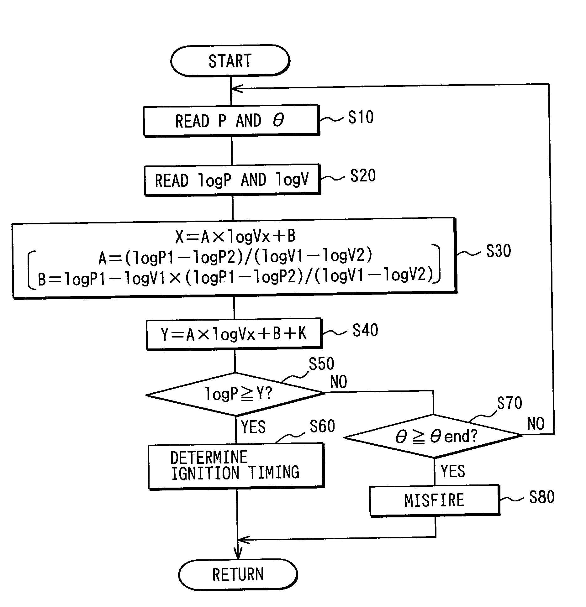
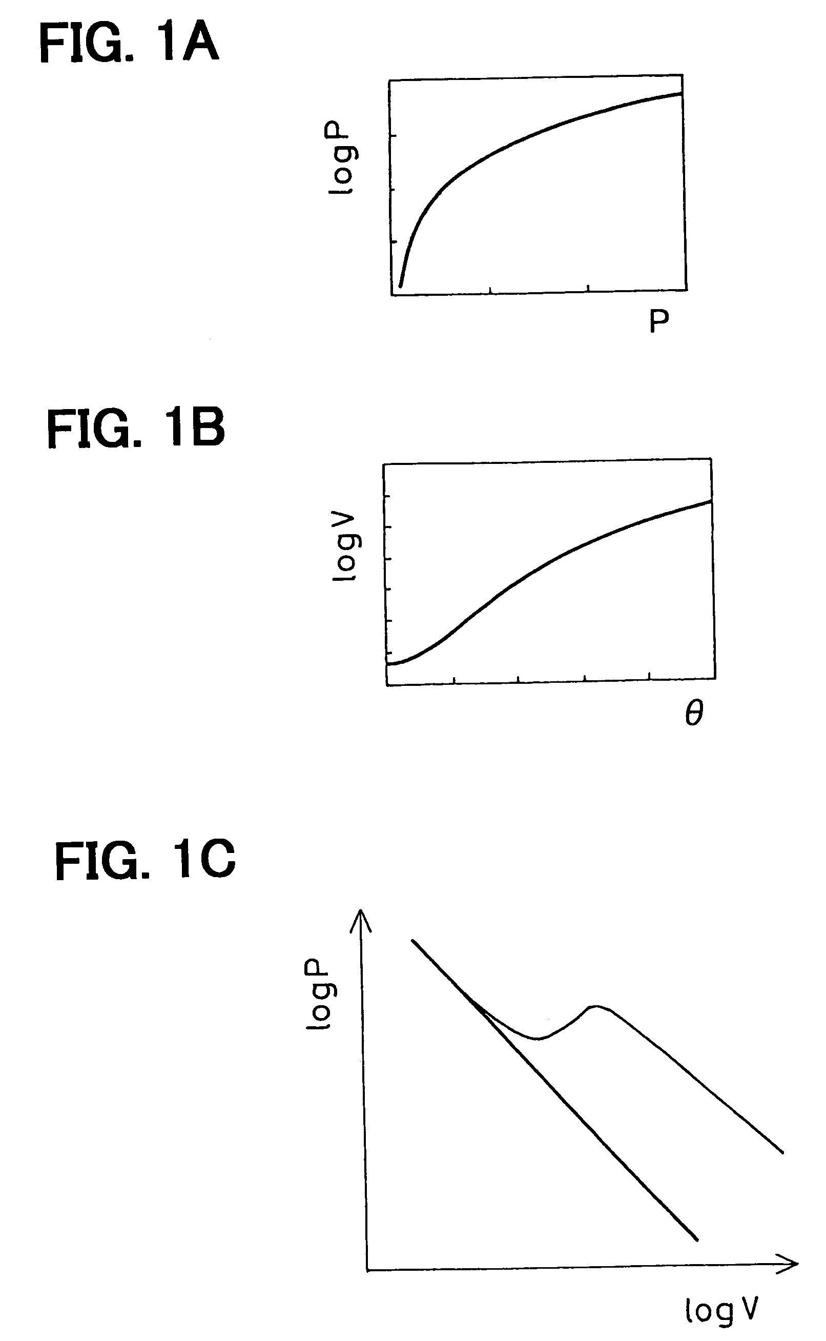
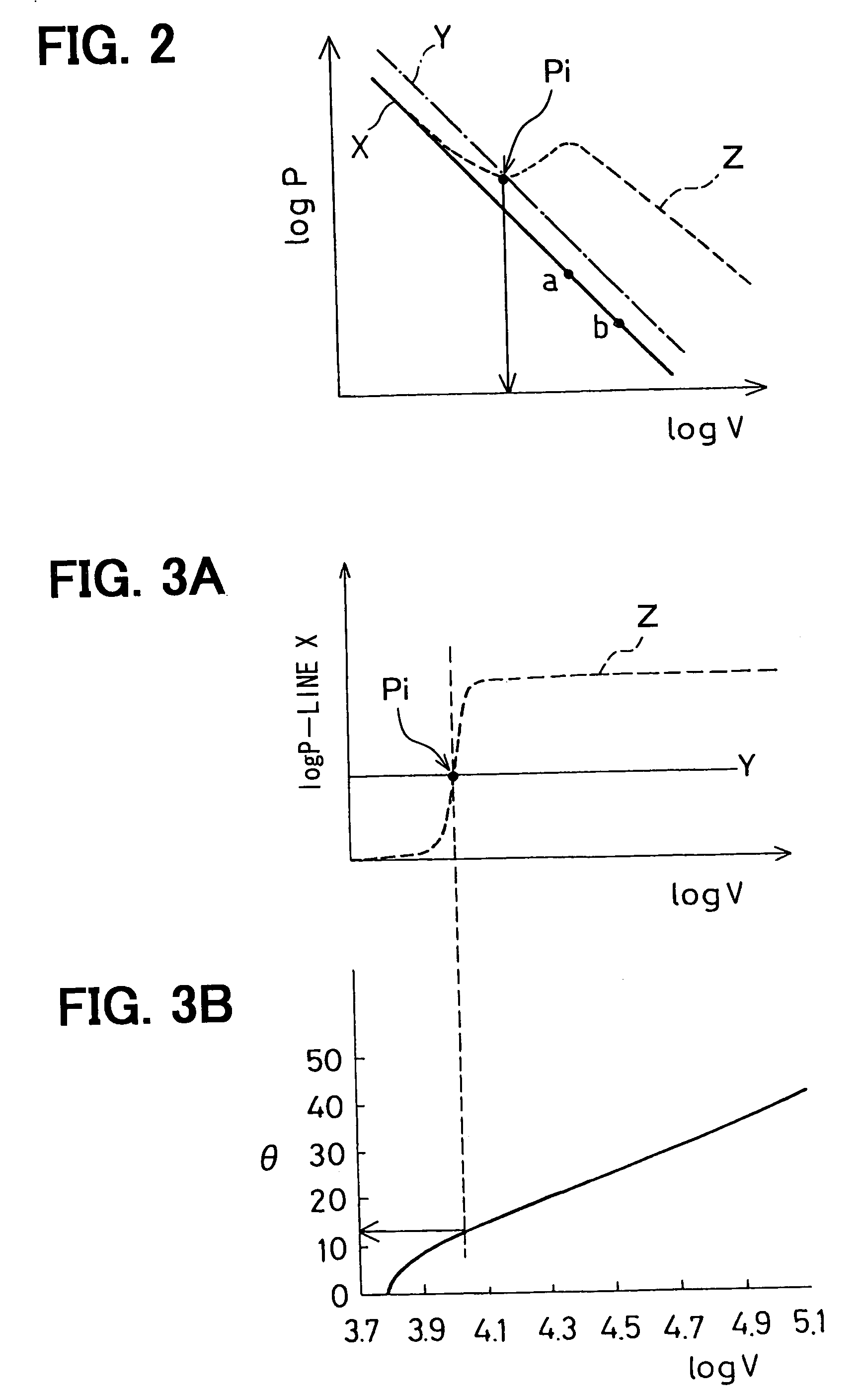
[0086]In the first embodiment, the cylinder pressure P and the cylinder volume V corresponding to the crank angle θ at least from the compression stroke to the combustion and expansion stroke are converted to the logarithmic value log P and the logarithmic value log V from the conversion map P and the conversion map V, respectively, and the logarithmic value log P and the logarithmic value log V are read from the logarithm maps, whereby a change in the cylinder pressure P from the compression stroke to the combustion and expansion stroke can be expressed as a logarithmic conversion waveform. This logarithmic conversion waveform is expressed by a straight line having a given gradient before a pressure rise developed by combustion in the cylinder starts, that is, while the cylinder pressure P varies according to only the motion of the piston 4. Therefore, the motoring waveform can be easily estimated from the logarithmic conversion waveform by a linear appr...

second embodiment

[Second Embodiment]

[0090]In this second embodiment, one example will be described in which a plurality of injections are sprayed during one combustion stroke, for example, the second injection is sprayed after the first injection and in which an ignition timing Tburn to the second injection is sensed.

[0091]For example, as shown in FIG. 6A, when the second injection or a main injection Qm is sprayed after the first injection or a pilot injection Qp, as shown in FIG. 6B, a pressure rise developed by the combustion of the main injection Qm occurs after a pressure rise developed by the combustion of the pilot injection Qp and hence a logarithmic conversion waveform varies in the manner shown in FIG. 7. In this case, when the determination line Y of the ignition timing Tburn to the main injection Qm (second injection) is computed by using the motoring waveform as the base line X as described in the first embodiment, the determination line varies for each combustion cycle because of the e...

third embodiment

[Third Embodiment]

[0096]In this third embodiment, a method of determining a combustion finishing timing will be described.

[0097]As described in the first embodiment, before a pressure rise developed by combustion in the cylinder starts, that is, while the cylinder pressure P changes according to only the motion of the piston 4, PVn=constant (where P is cylinder pressure and V is cylinder volume and n is polytropic exponent). For this reason, the logarithmic conversion waveform (motoring waveform) shown in the logarithm map, as shown in FIG. 9, is expressed by a straight line having a given gradient. Here, when the gradient of the logarithmic conversion waveform to the logarithmic value log V is expressed by a graph, as shown in FIG. 10 (the vertical axis is gradient and the horizontal axis is logarithmic value log V), the motoring waveform (base line X described in the first embodiment) is expressed by a straight line having a constant gradient and parallel to the horizontal axis in...


PUM


Abstract

An ECU converts a cylinder pressure P and a cylinder volume V corresponding to a crank angle θ at least from a compression stroke to a combustion and expansion stroke to a logarithmic value log P and a logarithmic value log V, respectively, to find a logarithmic conversion waveform and estimates a motoring waveform which is obtained by subtracting a pressure rise developed by combustion in a cylinder from the logarithmic conversion waveform, that is, corresponds to a non-combustion state. Further, the ECU computes a determination line Y of an ignition timing Tburn on the basis of the base line X of the estimated motoring waveform and determines the ignition timing Tburn on the basis of this determination line Y and the logarithmic conversion waveform.

Description

CROSS-REFERENCE TO RELATED APPLICATION[0001]This application is based on Japanese Patent Application No. 2004-172394 filed on Jun. 10, 2004 the disclosure of which is incorporated herein by reference.FIELD OF THE INVENTION[0002]The present invention relates to a controller for an internal combustion engine that detects an ignition timing (timing of starting combustion) of an internal combustion engine on the basis of outputs of a cylinder pressure sensor and a crank angle sensor.BACKGROUND OF THE INVENTION[0003]In an internal combustion engine such as a diesel engine and a gasoline engine, it is important to detect the ignition timing of fuel in a cylinder in order to optimally control a timing of injecting fuel into a cylinder. This ignition timing of fuel can be determined by comparing a cylinder pressure waveform when fuel is combusted with a cylinder pressure waveform when fuel is not combusted (referred to as a motoring waveform) (see JP-2001-55955A). Here, the motoring wavefor...

Claims


Application Information

Patent Timeline
Patent Type & Authority Patents(United States)
IPC IPC(8): G01M15/05F02D45/00F02D41/34F02D41/40F02P5/00F02P17/00
CPCF02D35/023F02D41/009F02D41/2419F02D35/028
Inventor KOHIRA, SUMIKOHARAGUCHI, HIROSHI
Owner DENSO CORP
Why Eureka
Try Eureka