Method for producing a combined packing container and a device for carrying out said method

a technology of combined packaging and packaging container, which is applied in the field of packaging technology, can solve the problems of difficult interlocking connection process, complex structure of moving gripper clamp, and easy faults

Inactive Publication Date: 2006-10-10
GREINER PACKAGING AG
View PDF3 Cites 13 Cited by
  • Summary
  • Abstract
  • Description
  • Claims
  • Application Information

AI Technical Summary

Benefits of technology

[0008]Another advantageous approach is one whereby the plastic inner part is loosely inserted in the outer part retained in a holder at a first station and the loosely inserted plastic inner part is then pushed into and interlocked with the outer part at a second station. This enables the production line to be operated at an even higher rate because the insertion process and the subsequent interlocking process are operated at different work stations.
[0027]However, another possibility is to provide at least one suction line in the insertion element, which opens into the free space or intermediate space left between the base of the plastic inner part and the insertion element, the suction line being connected to a vacuum generator. Consequently, when a vacuum pressure is generated accordingly, the base region of the plastic inner part is drawn in and collapses towards its interior, which enables the external cross-sectional dimension of the catch means to be reduced to the degree that the plastic inner part can be pushed in and down past the narrowest diameter or dimension of the outer part with only a light pushing action.

Problems solved by technology

The process of making the interlocked connection is problematic because the relatively thin-walled plastic inner part is susceptible to deformation.
However, this approach is not without problems.
Firstly, a moving gripper clamp is complicated in structure and susceptible to faults.
Furthermore, the image printed on the external face of the outer part, which is generally of a high quality, can easily be damaged during the gripping process.
Secondly, the assembly process can be operated at relatively limited rates only if using a gripper clamp, which means that several identical stations have to be operated in parallel to obtain a high throughput, which is expensive.

Method used


Image

  • Method for producing a combined packing container and a device for carrying out said method
  • Method for producing a combined packing container and a device for carrying out said method
  • Method for producing a combined packing container and a device for carrying out said method

Examples


Embodiment Construction

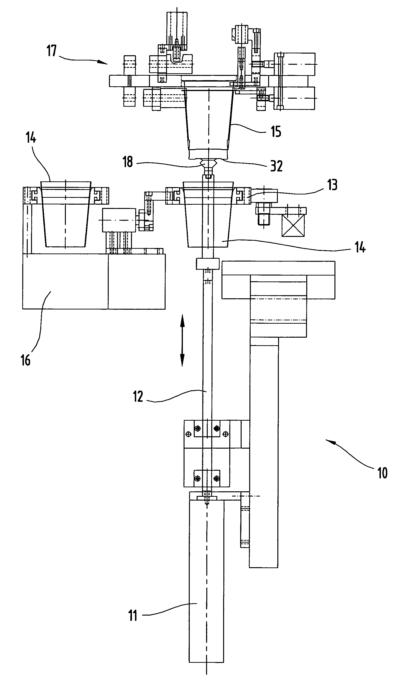
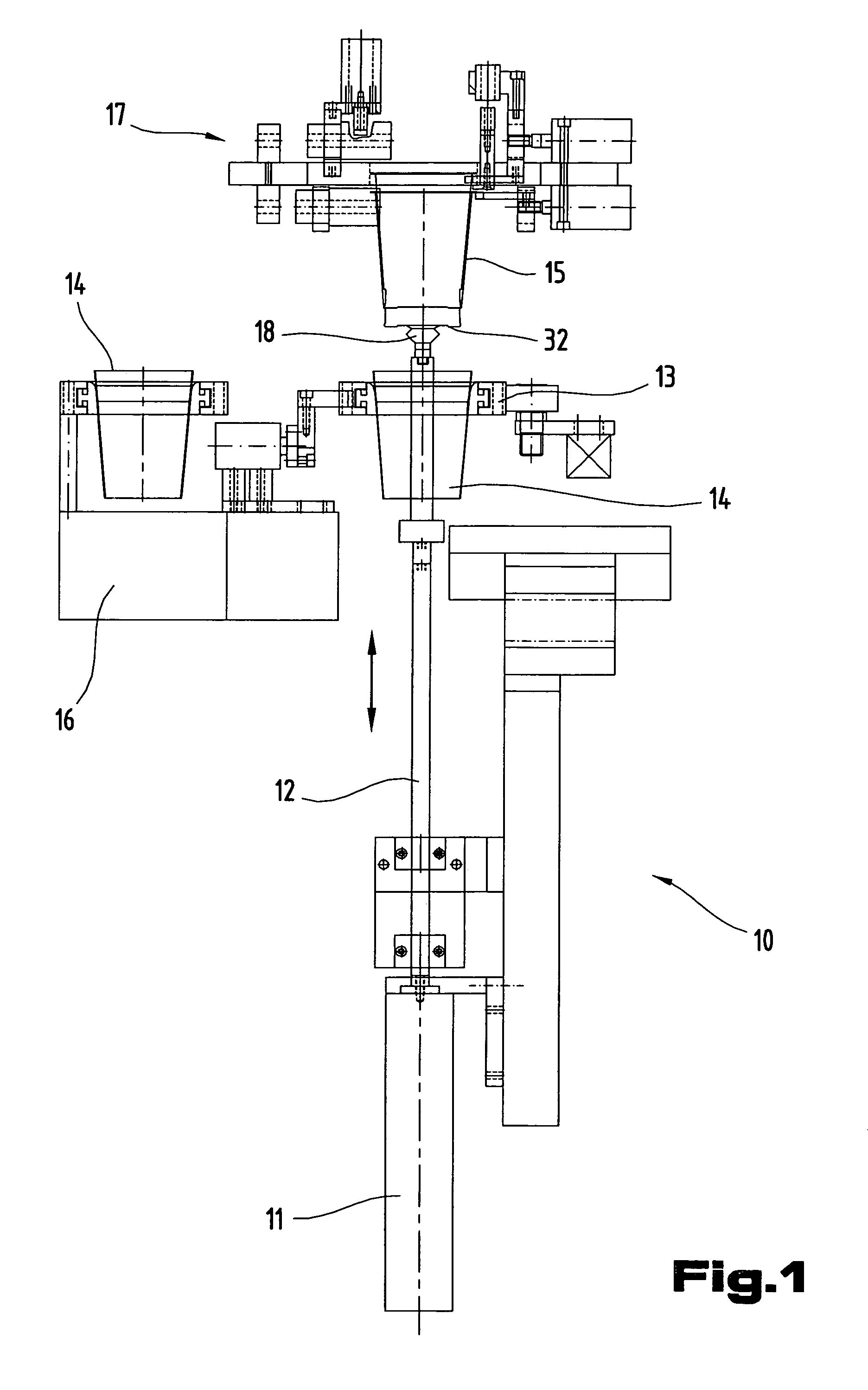
[0006]Accordingly, the objective of the invention is to propose a method for producing combination packaging containers joined in an interlocked arrangement, which can be operated reliably but with less machinery, whilst simultaneously enabling a high throughput rate with a high degree of operating reliability, as well as a system for implementing this method.

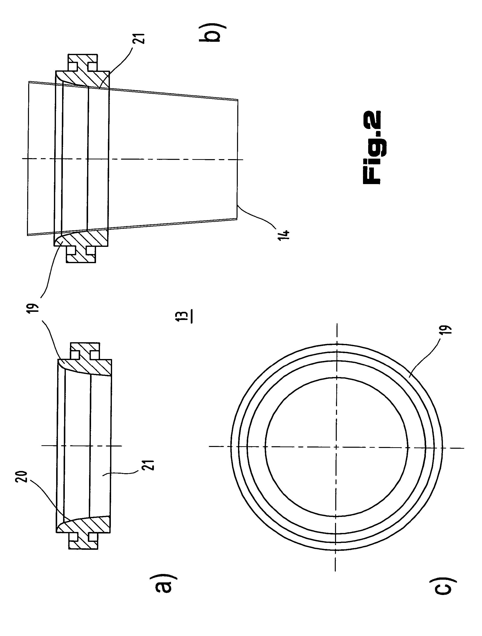
[0007]This objective is achieved as a result of all the features outlined in claims 1 and 21. The essential aspect of the invention is based on the fact that the outer part is held in a holder and the plastic inner part is firstly introduced into the outer part retained in the holder, in particular is loosely inserted in it, and the outer part is then pushed in so that it interlocks, the plastic inner part and the outer part preferably being of a conical shape, tapering towards the base—in other words towards the bottom as seen in the normal position of usage. Consequently, depending on the selected assembly position, the plast...


PUM

PropertyMeasurementUnit
distanceaaaaaaaaaa
heightaaaaaaaaaa
internal diameteraaaaaaaaaa

Abstract

As part of a method for producing a combination packaging container (28), which combination packaging container (28) comprises a beaker-shaped plastic inner part (15) and a casing-type outer part (14) surrounding the plastic inner part (15) and retained on the external face of the plastic inner part (15) in an interlocking arrangement, and by which method the two parts (14, 15) are pushed one in the other in an interlocking arrangement, the assembly process is improved due to the fact that the outer part (14) is retained in a holder (13) and the plastic inner part (15) is introduced into the outer part (14) retained in the holder (13) and then pushed down into the outer part (14) so as to interlock.

Description

CROSS REFERENCE TO RELATED APPLICATIONS[0001]Applicants claim priority under 35 U.S.C. 119 of SWITZERLAND Application No. 35 / 02 filed on Jan. 10, 2002. Applicants also claim priority under 35 U.S.C. § 365 of PCT / EP03 / 00174 filed on Jan. 10, 2003. The international application under PCT article 21(2) was not published in English.FIELD OF THE INVENTION[0002]The present invention falls within the field of packaging technology. It relates to a method of producing a combination packaging container of the type outlined in the generic part of claim 1 and a device for implementing the method.THE PRIOR ART[0003]A combination packaging container is known from an earlier patent application, WO 98 / 13270 A1, filed by the present applicant, in which a beaker-shaped plastic inner part and a casing-type outer part (e.g. made from cardboard) are initially made separately and then inserted one inside the other and interlocked with one another to form the final container. The process of making the int...

Claims


Application Information

Patent Timeline
Patent Type & Authority Patents(United States)
IPC IPC(8): B21D39/00B21D39/03B31B1/60B31B7/00B31B50/00B31B105/00B31B120/40
CPCB31B7/00B31B2217/0046Y10T29/49908Y10T29/49829Y10T29/49936B31B50/00B31B2105/00B31B2120/402B31B50/73
Inventor SCHELLENBERG, WALTER
Owner GREINER PACKAGING AG
Why Eureka
Try Eureka