Torque detecting apparatus

a technology of torque detection and detecting apparatus, which is applied in the direction of instruments, force/torque/work measurement apparatus, transportation and packaging, etc., can solve the problem of low damage possibility of holding cylinders, and achieve the effect of accurately detecting torque and low damage possibility

Inactive Publication Date: 2006-10-10
KOYO SEIKO CO LTD +1
View PDF6 Cites 8 Cited by
  • Summary
  • Abstract
  • Description
  • Claims
  • Application Information

AI Technical Summary

Benefits of technology

[0011]The present invention has been made with the aim of solving the above problems, and it is an object thereof to provide a torque detecting apparatus which can effect torque detection accurately even when pressure applied to a projection provided at the torque detecting apparatus is changed, and the possibility for damage is low even when a large pressure or impact is applied to the projection.
[0013]According the present invention, the axial portion of the holding cylinder which does not have the recess, i.e. a portion which does not have a recess inside thereof, has a thickness larger than a portion which has the recess inside thereof. Consequently, when pressure in the radial direction of the holding cylinder is applied to the projection, the stress applied from the projection to the holding cylinder is dispersed widely in comparison with a holding cylinder comprising a projection on an outer surface portion having a recess inside thereof, so that deformation of the holding cylinder due to the stress can be suppressed. Accordingly, a change in the inductance of the coil due to a change in the pressure applied to the projection can be suppressed. Moreover, when pressure in the radial direction of the holding cylinder is applied to the projection, the stress applied to the holding cylinder is dispersed widely in comparison with a holding cylinder comprising a projection on an outer surface portion having a recess inside thereof. Accordingly, the possibility for damage to the holding cylinder is low even when a large pressure in the radial direction of the holding cylinder is applied to the projection during attaching the torque detecting apparatus at a predetermined position.
[0015]According to the present invention, when pressure in the radial direction of the holding cylinder is applied to the projection, the stress applied to the holding cylinder is applied evenly to the two recesses centering around the axial portion which separates the two recesses. Accordingly, the effect of the pressure applied to the projection is applied evenly to the coil and the compensating coil respectively and a change in the inductance of the coil due to the pressure is at the same level as a change in the inductance of the compensating coil. Consequently, the value of the inductance of the coil with respect to the compensating coil is not changed in a large way even when pressure in the radial direction of the holding cylinder is changed.
[0017]According to the present invention, a holding cylinder can be constructed by holding the coil and the compensating coil in the two cylinder portions and interposing the intermediate between the two cylinder portions, so that the coil and the compensating coil can be held in the holding cylinder easily.
[0019]According to the present invention wherein a plurality of projections are arranged at regular intervals in the circumferential direction of the holding cylinder, when pressure at the same level is applied to the respective projections, the stress applied to the holding cylinder is dispersed widely and equally in comparison with a holding cylinder provided with a plurality of projections arranged at irregular intervals in the circumferential direction of the holding cylinder. Accordingly, deformation of the holding cylinder due to the pressure and a change in the inductance of the coil due to the deformation can be suppressed.
[0020]With the torque detecting apparatus according to the present invention, the detected value of torque does not fluctuate even when the pressure applied to the projection is changed, so that a torque inputted into the input shaft can be detected accurately. For example, when the torque detecting apparatus is supported within a housing constituting an electric power steering apparatus, the detected value of torque does not fluctuate even when the temperature of the electric power steering apparatus and the torque detecting apparatus is changed, so that a torque inputted into the input shaft can be detected accurately and favorable feeling in steering can be maintained. Moreover, the holding cylinder can be free from the possibility of damage due to a large pressure or impact applied to the projection. For example, during attaching the torque detecting apparatus within a housing constituting an electric power steering apparatus, the holding cylinder can be pressed into the housing with a large force, so that the torque detecting apparatus can be attached in a stable manner. Furthermore, the coil and the compensating coil can be held in the holding cylinder easily, so that the torque detecting apparatus can be assembled effectively.

Problems solved by technology

Accordingly, the possibility for damage to the holding cylinder is low even when a large pressure in the radial direction of the holding cylinder is applied to the projection during attaching the torque detecting apparatus at a predetermined position.

Method used


Image

  • Torque detecting apparatus
  • Torque detecting apparatus
  • Torque detecting apparatus

Examples


Embodiment Construction

[0028]The following description will explain the present invention in detail with reference to the drawings illustrating an embodiment thereof.

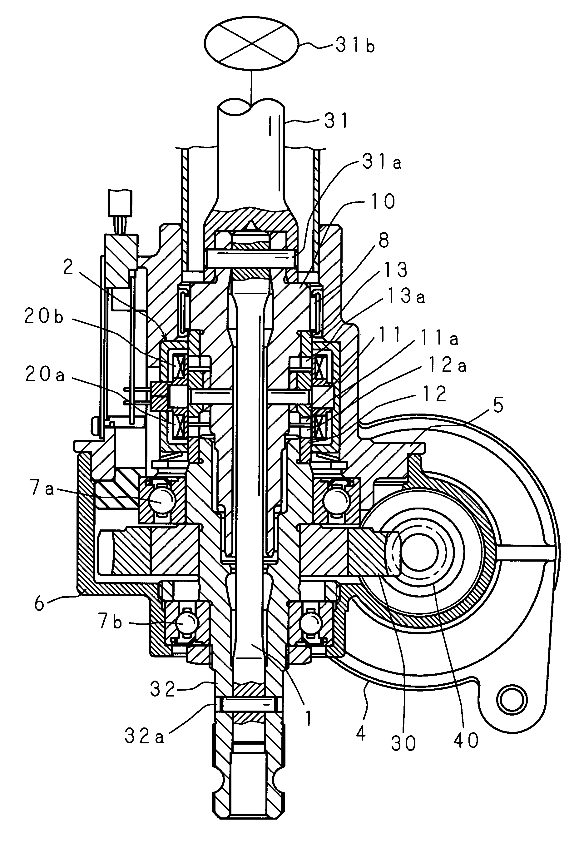
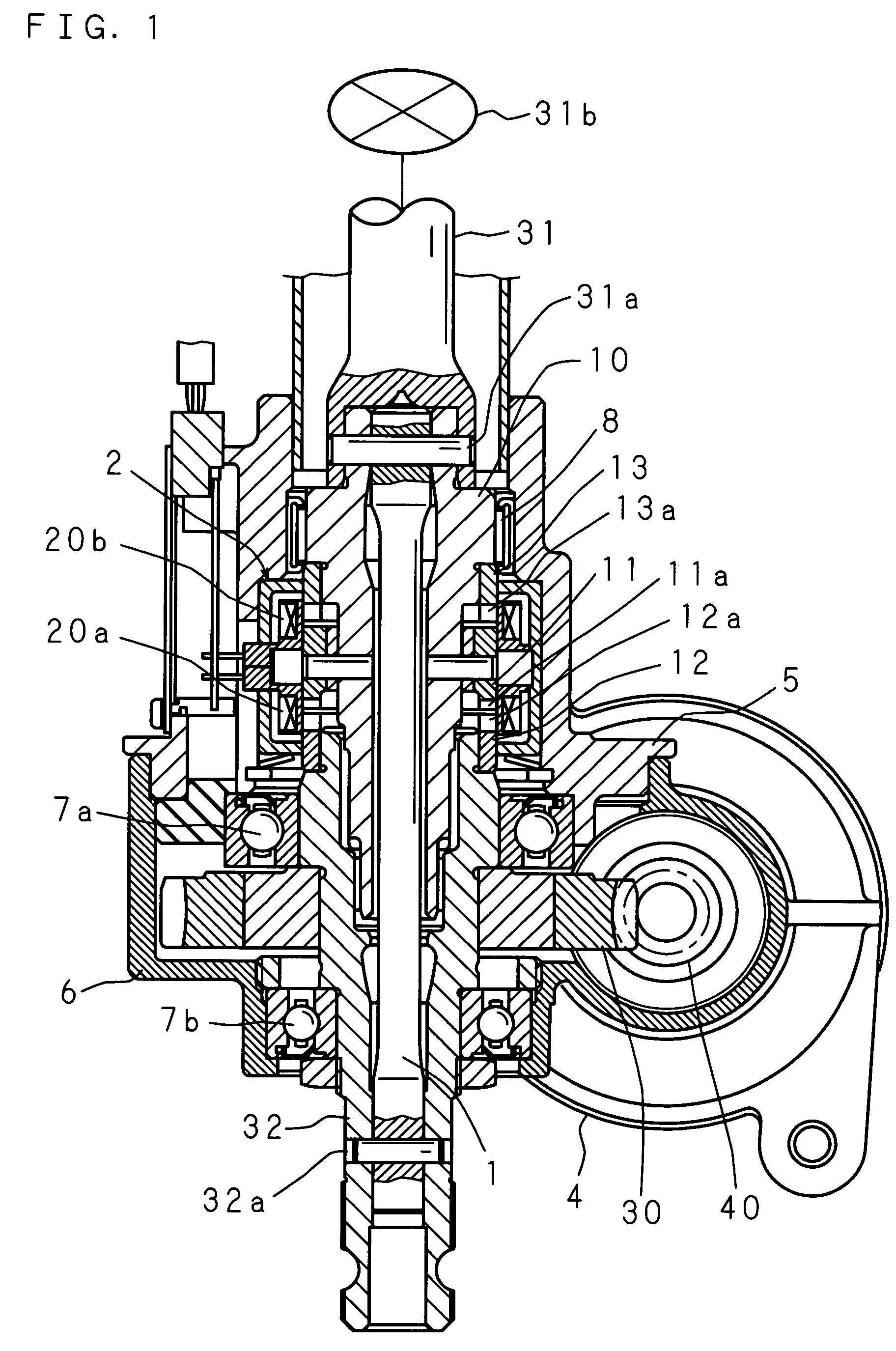
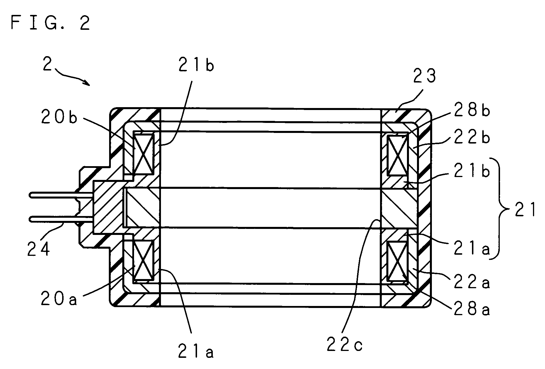
[0029]FIG. 1 is a schematic sectional view of an electric power steering apparatus comprising a torque detecting apparatus according to the present invention, seen from a side of a vehicle. The torque detecting apparatus according to the present invention comprises: an input shaft 10 to which a torque is inputted; an output shaft 32 for outputting the torque inputted into the input shaft 10; a connecting shaft 1 of a torsion bar for connecting the input shaft 10 and the output shaft 32 to transmit the torque; a coil 20a for detecting a torsional angle of the connecting shaft 1 which arises due to a torque applied to the connecting shaft 1; a compensating coil 20b for applying temperature compensation to the torque detection by the coil 20a; and a holding cylinder 2 for holding, respectively, the coil 20a and the compensating coil 20b coaxiall...


PUM

PropertyMeasurementUnit
diameteraaaaaaaaaa
diameteraaaaaaaaaa
thicknessaaaaaaaaaa

Abstract

The torque detecting apparatus comprises an input shaft to which a torque is inputted, an output shaft for outputting the inputted torque, a connecting shaft for connecting the input shaft and the output shaft to transmit the torque, a coil for detecting a torque applied from the input shaft to the connecting shaft based on a torsional angle which arises at the connecting shaft, and a holding cylinder for holding the coil coaxially, wherein the holding cylinder has inside thereof a recess extending in the circumferential direction, and the coil is fitted in the recess. Projections for supporting the holding cylinder at a predetermined position are provided on the outer surface of an axial portion which does not have the recess. Accurate torque detection can be effected even when pressure applied to the projections provided at the holding cylinder constituting the torque detecting apparatus is changed.

Description

CROSS-REFERENCE TO RELATED APPLICATIONS[0001]This Nonprovisional application claims priority under 35 U.S.C. §119(a) on Patent Application No. 2004-6095 filed in Japan on Jan. 13, 2004, the entire contents of which are hereby incorporated by reference.BACKGROUND OF THE INVENTION[0002]The present invention relates to a torque detecting apparatus, and in particular to a noncontact torque detecting apparatus for detecting a torque applied to a connecting shaft by detecting a torque inputted into an input shaft as a change in the inductance of a coil due to torsion which arises at the connecting shaft.[0003]A torque detecting apparatus comprises: an input shaft to which a torque is inputted; an output shaft for outputting the inputted torque; a connecting shaft of a torsion bar for connecting the input shaft and the output shaft; and a coil, which surrounds the connecting shaft, the input shaft and the output shaft, for detecting a torque applied from the input shaft to the connecting s...

Claims


Application Information

Patent Timeline
Patent Type & Authority Patents(United States)
IPC IPC(8): G01L3/02G01L3/10G01L3/12G01L3/14B62D6/10G01L5/22
CPCB62D6/10G01L3/101G01L5/221G01L3/105
Inventor NAKATANI, NORIOSANADA, TAKAHIROYAMAMOTO, MASAYUKI
Owner KOYO SEIKO CO LTD
Why Eureka
Try Eureka