Autopurge printing system

a printing system and autopurge technology, applied in printing and other directions, can solve the problems of clogging, restricting, or blocking certain orifices, and accumulating debris in the printface, or accumulating dust, dirt, dried ink and other waste materials,

Active Publication Date: 2006-10-10
VIDEOJET TECH INC
View PDF278 Cites 24 Cited by
  • Summary
  • Abstract
  • Description
  • Claims
  • Application Information

AI Technical Summary

Benefits of technology

[0014]Certain embodiments of the present invention also provide a method of automatically cleaning a printhead of an inkjet printer. The method includes engaging a first solenoid assembly to constrict a solvent supply line, pulsing solvent through a portion of the solvent supply line that is downstream from the first solenoid assembly due to said engaging, and running the solvent over an orifice plate of the printhead through a solvent port that is in fluid communication with the solvent supply line, wherein the running removes debris from the orifice plate. The method may also include opening a downstream check valve due to the engaging step so that solvent may pass through the downstream check valve, and closing an upstream check valve due to the engaging step so that solvent may not pass through the upstream check valve.

Problems solved by technology

Due to the fact that ink is not ejected through all of the orifices during a printing process, the orifices that are less frequently used may accumulate dust, dirt, dried ink, and other waste materials over time.
Certain orifices may become crusted over, restricted, or blocked because of infrequent use, or simply because the printing system may be idle for an extended period of time.
Additionally, the printface, in general, may also accumulate debris, such as dust, dirt, paper debris, and the like.
In general, however, a user still needs to collect the ink and waste materials after they have been passed through the orifices.
Such a process, however, is inefficient and time-consuming.

Method used


Image

  • Autopurge printing system
  • Autopurge printing system
  • Autopurge printing system

Examples


Embodiment Construction

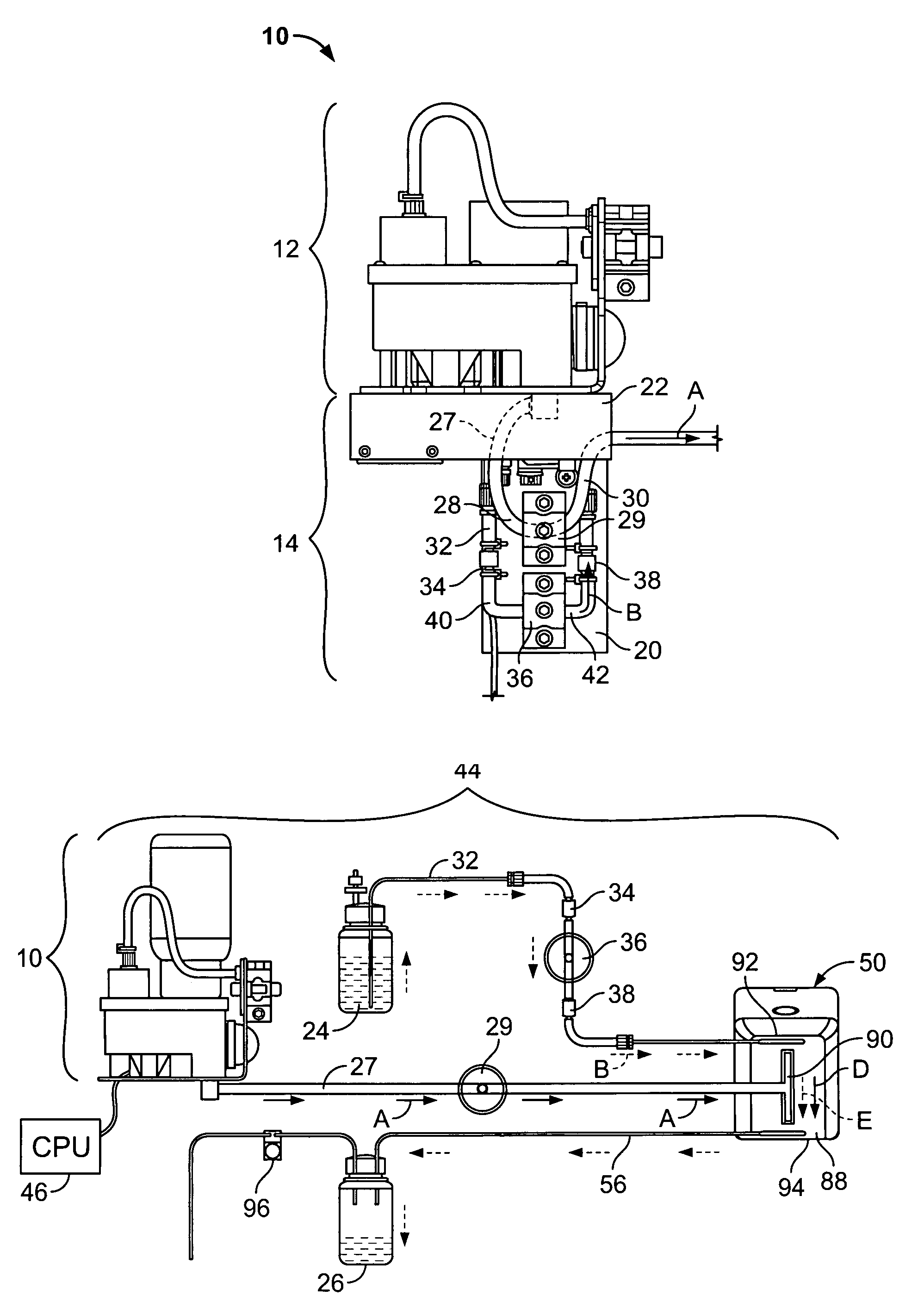
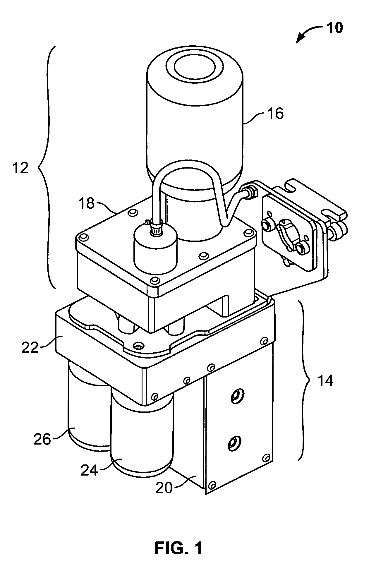
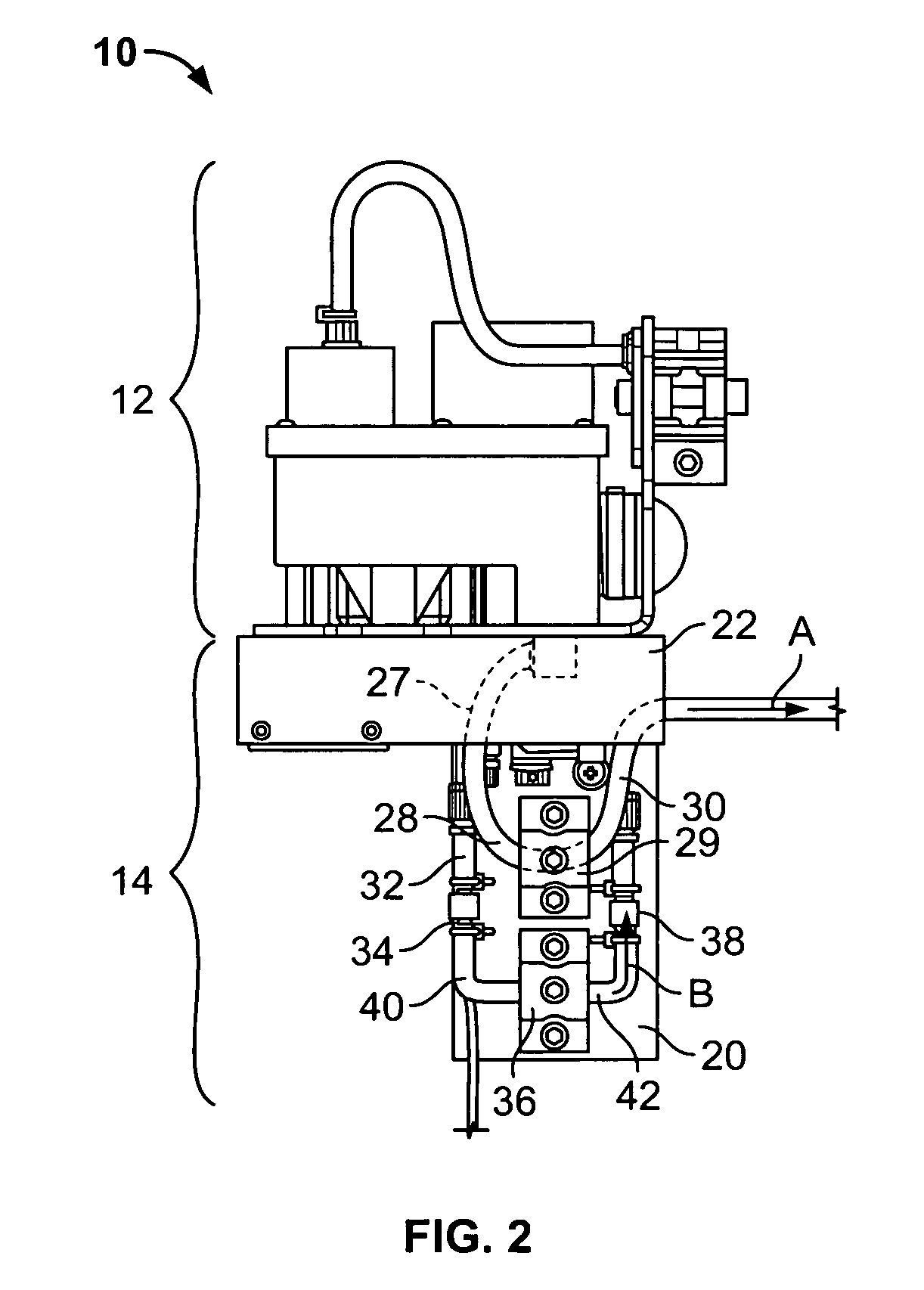
[0026]FIG. 1 illustrates an isometric view of an autopurge ink system 10, according to an embodiment of the present invention. The system 10 may be used with a drop-on-demand inkjet printer. The system 10 includes an ink supply system 12 mounted on an autopurge unit 14. The ink supply system 12 includes an ink bottle 16 in communication with an ink reservoir 18, such that ink passes from the ink bottle 16 into the ink reservoir 18. The autopurge unit 14 includes a solenoid housing 20 connected to a ink supply system support housing 22. A solvent supply bottle 24 and a waste container 26 are removably mounted to the ink supply system support housing 22. For example, the solvent supply bottle 24 and the waste container 26 may threadably engage corresponding reciprocal threaded engagement ports (not shown) located on said ink supply system support housing 22. Thus, the solvent supply bottle 24 and the waste container 26 may be threaded onto and removed from the ink supply system suppor...


PUM


Abstract

A system, including an ink supply system configured to supply ink to a printhead; and an autopurge unit configured to automatically clean the printhead. The autopurge unit includes a solvent supply in fluid communication with a solvent line, a solenoid housing, and a waste container. The solenoid housing includes a first solenoid assembly disposed within an ink line, wherein the ink line is in fluid communication with the ink supply and a first outlet that is configured to be in fluid communication with the printhead; and a second solenoid assembly disposed within a solvent line. The waste container is in fluid communication with a waste delivery line having a waste inlet. The waste inlet is configured to be in fluid communication with a waste line that is in communication with the printhead so that fluid waste from the printhead is deposited into the waste container.

Description

BACKGROUND OF THE INVENTION[0001]Embodiments of the present invention generally relate to an inkjet printer, and more particularly, to an inkjet printer having an autopurge system configured to automatically clean a printhead.[0002]Drop-on-demand inkjet printers include a printhead having a binary array having a large number of print orifices. During printing, ink is ejected through particular orifices based on the nature of a character to be printed on a suitable medium. Ink is not ejected through every orifice at all times during a printing process. Rather, only select orifices are utilized at any one time depending on the nature of the character to be printed. Generally, drop-on-demand inkjet printers differ from continuous inkjet printers, in which a constant stream of drops are passed between charged electrodes, because ink is not ejected through all of the orifices during a particular printing process.[0003]Due to the fact that ink is not ejected through all of the orifices du...

Claims


Application Information

Patent Timeline
Patent Type & Authority Patents(United States)
IPC IPC(8): B41J2/015B41J2/165
CPCB41J2/16552
Inventor KUESTER, KEVIN W.KNIEPKAMP, LAWRENCE E.VOSS, TERRYHELLER, JACK
Owner VIDEOJET TECH INC
Why Eureka
Try Eureka