Pressurized oil supply for propeller engine system

a propeller engine and pressurized oil technology, which is applied in the direction of pressure lubrication, liquid fuel engine components, wind motors with perpendicular air flow, etc., can solve the problems of not being able to maintain an adequate rgb lubrication system oil supply and required pressurized oil flow

Active Publication Date: 2006-10-10
PRATT & WHITNEY CANADA CORP
View PDF20 Cites 43 Cited by
  • Summary
  • Abstract
  • Description
  • Claims
  • Application Information

AI Technical Summary

Problems solved by technology

During non-feathered operation, it may not be possible for the RGB lubrication system to maintain an adequate oil supply to the propeller pump, because during engine shutdown conditions, the engine spool driving the propeller pump is either stationary or rotating at very low speeds and, hence, unlikely to provide the required pressurized oil flow required at the propeller pump inlet.

Method used


Image

  • Pressurized oil supply for propeller engine system
  • Pressurized oil supply for propeller engine system
  • Pressurized oil supply for propeller engine system

Examples


Embodiment Construction

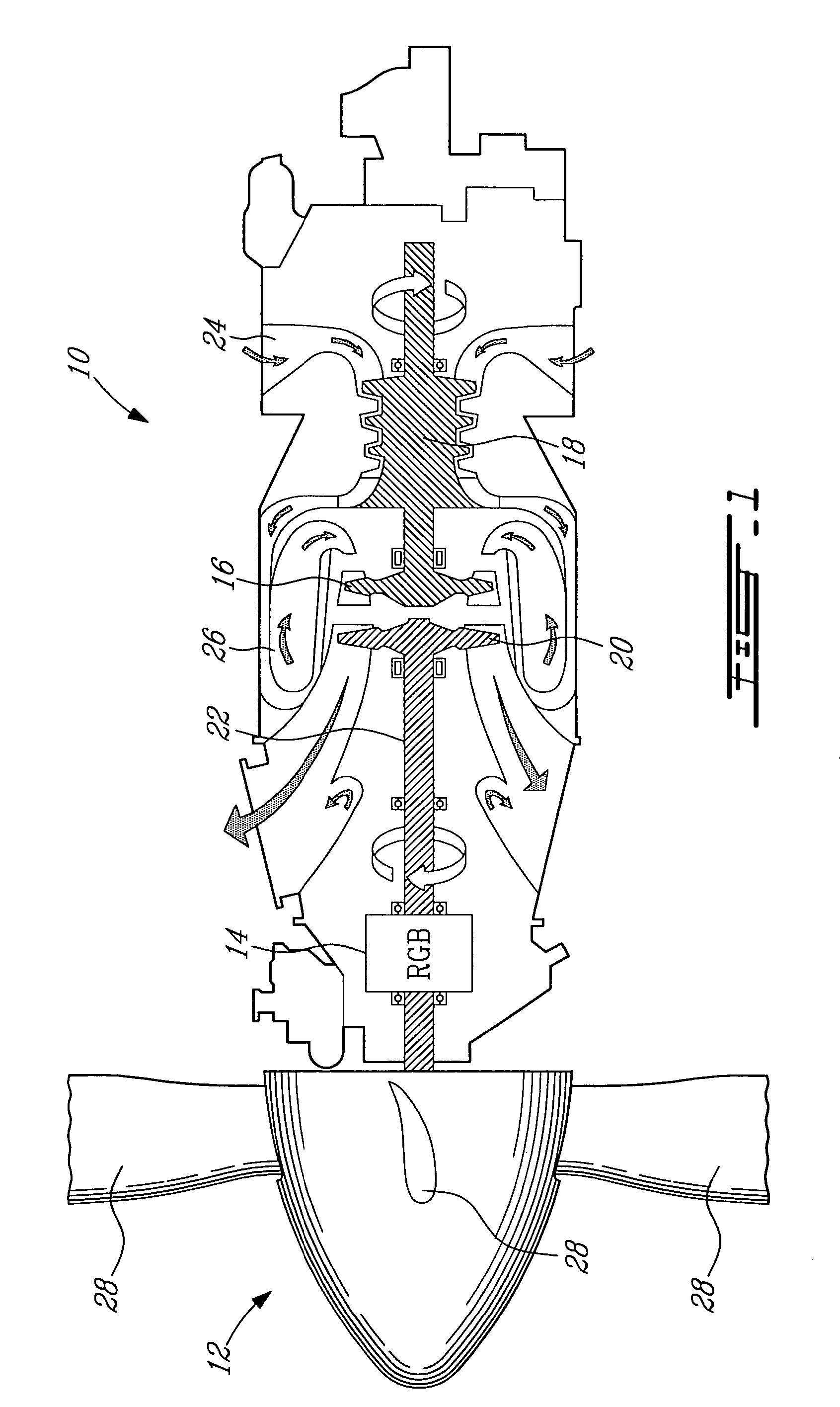
[0016]FIG. 1 illustrates a turboprop engine 10 of a type preferably provided for use in subsonic flight to drive a propeller 12 via a reduction gear box (RGB) 14. The engine 10 comprises a first rotating assembly consisting of a turbine 16 and a compressor 18, and a second rotating assembly consisting of a power turbine 20 mounted on a power turbine shaft 22. The first and second rotating assemblies are not connected together and turns at different speed and in opposite directions. This design is referred, to as a “free turbine engine”. It is understood that the present invention could be applied to other types of propeller engines as well.

[0017]The compressor 18 draws air into the engine 10 via an annular plenum chamber 24, increases its pressure and delivers it to a combustor 26 where the compressed air is mixed with fuel and ignited for generating a stream of hot combustion gases. The compressor turbine 16 extracts energy from the hot expanding gases for driving the compressor 18...


PUM


Abstract

A system and method for providing pressurised oil during non-feathered in-flight shutdown conditions in a variable-pitch aircraft propeller engine. A secondary pump provides pressurised oil substantially independent of an engine main oil circuit.

Description

BACKGROUND OF THE INVENTION[0001]1. Field of the Invention[0002]The present invention relates to a system and method for providing pressurized oil during non-feathered in-flight shutdown conditions in a variable-pitch aircraft propeller engine.[0003]2. Description of the Prior Art[0004]Propeller control systems for turboprop engines normally employ pressurized oil as a means of system actuation. The source of this pressurized oil is usually from a positive displacement or other pump which is driven from the propeller reduction gearbox (RGB) of the engine. The oil supply for this pump is typically provided by the RGB lubrication system, which is sized to ensure that the oil supply requirements of the propeller pump are satisfied during normal engine operating conditions.[0005]During in-flight engine shutdown conditions, it may be required to operate the propeller in a non-feathered or rotating condition and under these conditions it is desirable to have a functioning propeller contro...

Claims


Application Information

Patent Timeline
Patent Type & Authority Patents(United States)
IPC IPC(8): B64C11/40B64C11/42B63H1/00B64C11/38F02C7/32
CPCB64C11/38F02C7/32F05D2220/34F16N7/40F16N2260/00
Inventor WADDLETON, DAVID
Owner PRATT & WHITNEY CANADA CORP
Why Eureka
Try Eureka