Side-delivery suppository dispenser

a dispenser and suppository technology, applied in the field of dispensers, can solve the problems of improper placement of the suppository within the body cavity, irritation and pain of patients,

Inactive Publication Date: 2006-10-10
B BRAUN MEDICAL
View PDF45 Cites 31 Cited by
  • Summary
  • Abstract
  • Description
  • Claims
  • Application Information

AI Technical Summary

Problems solved by technology

This tapered end is often the cause of irritation and pain to the patient.
Furthermore, conventional applicators do not offer a feature by which a patient can determine whether or not the suppository has been fully dispensed, often resulting in improper placement of the suppository within the body cavity.

Method used


Image

  • Side-delivery suppository dispenser
  • Side-delivery suppository dispenser
  • Side-delivery suppository dispenser

Examples


Embodiment Construction

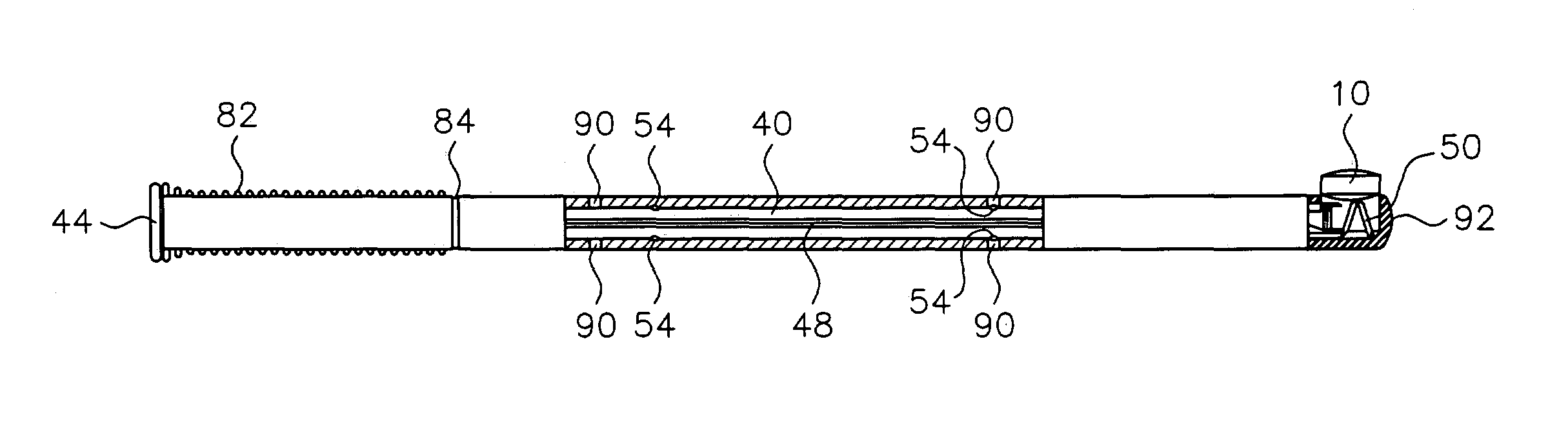
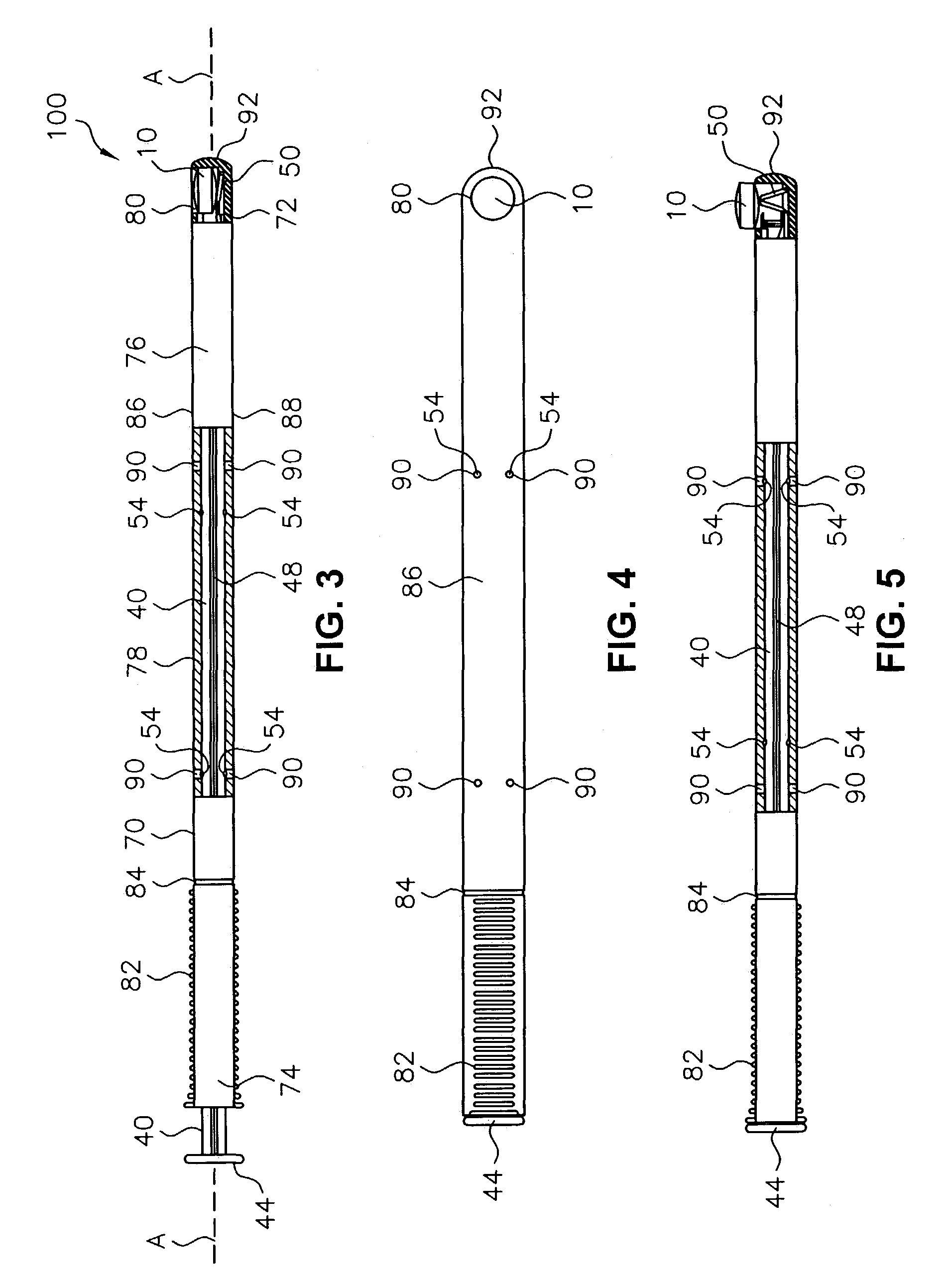
[0023]Referring now to the drawings, in which like reference numbers refer to like elements throughout the various figures that comprise the drawings, FIG. 3 is a partial cross-sectional side view of the dispenser 100 according to the present invention, as loaded with a tablet 10, with the plunger 40 as yet undepressed within the barrel 70. The dispenser 100 has two, main components: the barrel 70 and the plunger 40. Both the barrel 70 and the plunger 40 are preferably made of plastic material, most preferably plastics from the polyolefin family. Other flexible plastics could be used.

[0024]As illustrated in FIG. 3, the barrel 70 includes a head 72, a foot 74, and a body 76 having a length and extending between the head 72 and the foot 74. The barrel 70 further defines an axial passage 78 disposed along substantially the entire length of the body 76 beginning at the foot 74 and ending proximate the head 72, and includes a side aperture 80 providing external access through the body 76...


PUM


Abstract

A dispenser for delivering a suppository within a body cavity. The dispenser has two main components: a barrel and a plunger. The barrel includes a head, a foot, and a body having a length and extending between the head and the foot. The barrel further defines an axial passage disposed along substantially the entire length of the body beginning at the foot and ending proximate the head, and includes a side aperture providing external access through the body of the barrel to the axial passage at the head of the barrel. The plunger includes a nose, a tail, and a frame extending between the nose and the tail. The plunger is sized to travel within the axial passage of the barrel between a relaxed position and a compressed position, in which a suppository is ejected from the side aperture, upon actuation.

Description

FIELD OF THE INVENTION[0001]The present invention relates generally to instruments for medication delivery and, more particularly, to a dispenser for delivering a suppository within a body cavity.BACKGROUND OF THE INVENTION[0002]In the health care industry, there exist various methods by which medication can be given to a patient. These methods may require inhalation, injection, or application of the medication to a body cavity. More specifically, some types of medications require gradual adsorption in the body of a patient, and thus a suppository (generally in the form of a tablet) is introduced within a particular body cavity in order to meet this need. It is well known practice to administer such suppositories by use of manual applicators, which provide safe, hygienic, and controlled delivery of the suppository. It is desired that these manual applicators dispense the tablet upon actuation by the patient and leave the tablet in the dispensed location while and after the applicato...

Claims


Application Information

Patent Timeline
Patent Type & Authority Patents(United States)
IPC IPC(8): A61M25/00A61M31/00B65D83/04A61F13/20A61F13/26
CPCA61F13/26A61M31/007
Inventor LOOMIS, BENJAMIN N.
Owner B BRAUN MEDICAL
Why Eureka
Try Eureka