Translatable ultrasonic thermography inspection apparatus and method

a technology of ultrasonic thermography and inspection apparatus, applied in radiation thermography, optical radiation measurement, instruments, etc., can solve problems such as loss of structural integrity, dyes sometimes are not suitable for crack detection, and techniques have drawbacks

Inactive Publication Date: 2006-10-10
THE BOEING CO
View PDF4 Cites 35 Cited by
  • Summary
  • Abstract
  • Description
  • Claims
  • Application Information

AI Technical Summary

Problems solved by technology

Loss of structural integrity can be caused by material defects, such as disbonds, delaminations, cracks, corrosion, embedded contaminants, inclusions, and voids that can exist in a composite or monolithic component or structure.
This technique has drawbacks however.
The dye sometimes is not suitable to identify cracks that located in areas other than the surface of the component.
This technique requires point by point inspection, which can be labor intensive and is to some extent limited to only specific types of defects.
The resulting mechanical vibration of the subject under test tends to feature differential motion across the face of any defects that may be present, producing friction and causing the defects to heat up sharply, while defect-free areas of the test subject tend to be only minimally and uniformly heated by the vibration.
Some presently available analysis systems employing ultrasonic thermography techniques have drawbacks and limitations, however.
For example, some presently available ultrasonic thermography systems can analyze only small specimens, and are generally restricted to laboratory use.
Some other such systems require manual placement, orientation, and application of force between the transducer and the test surface, which requirements can degrade the repeatability, accuracy, and noninvasive nature of the technique.
That is, too much or too little pressure applied to the transducer during a pulse may degrade the repeatability of detection, while misalignment of the transducer can cause the part or surface being inspected to be cut or burned, or can cause damage to surface finishes.
Such systems are thus not always well suited for field inspection of materials or components, or for inspection of large objects, such as fuselages and flight control structures of in-service airplanes.

Method used


Image

  • Translatable ultrasonic thermography inspection apparatus and method
  • Translatable ultrasonic thermography inspection apparatus and method
  • Translatable ultrasonic thermography inspection apparatus and method

Examples


Embodiment Construction

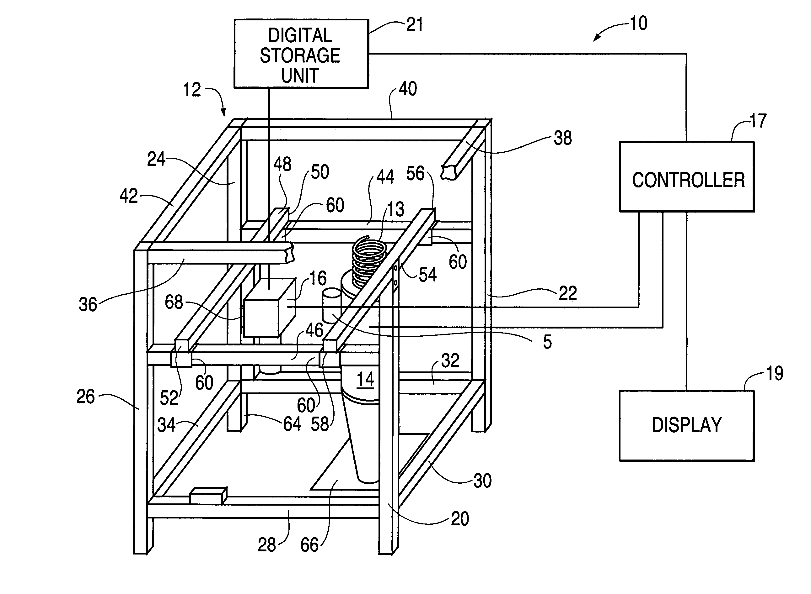
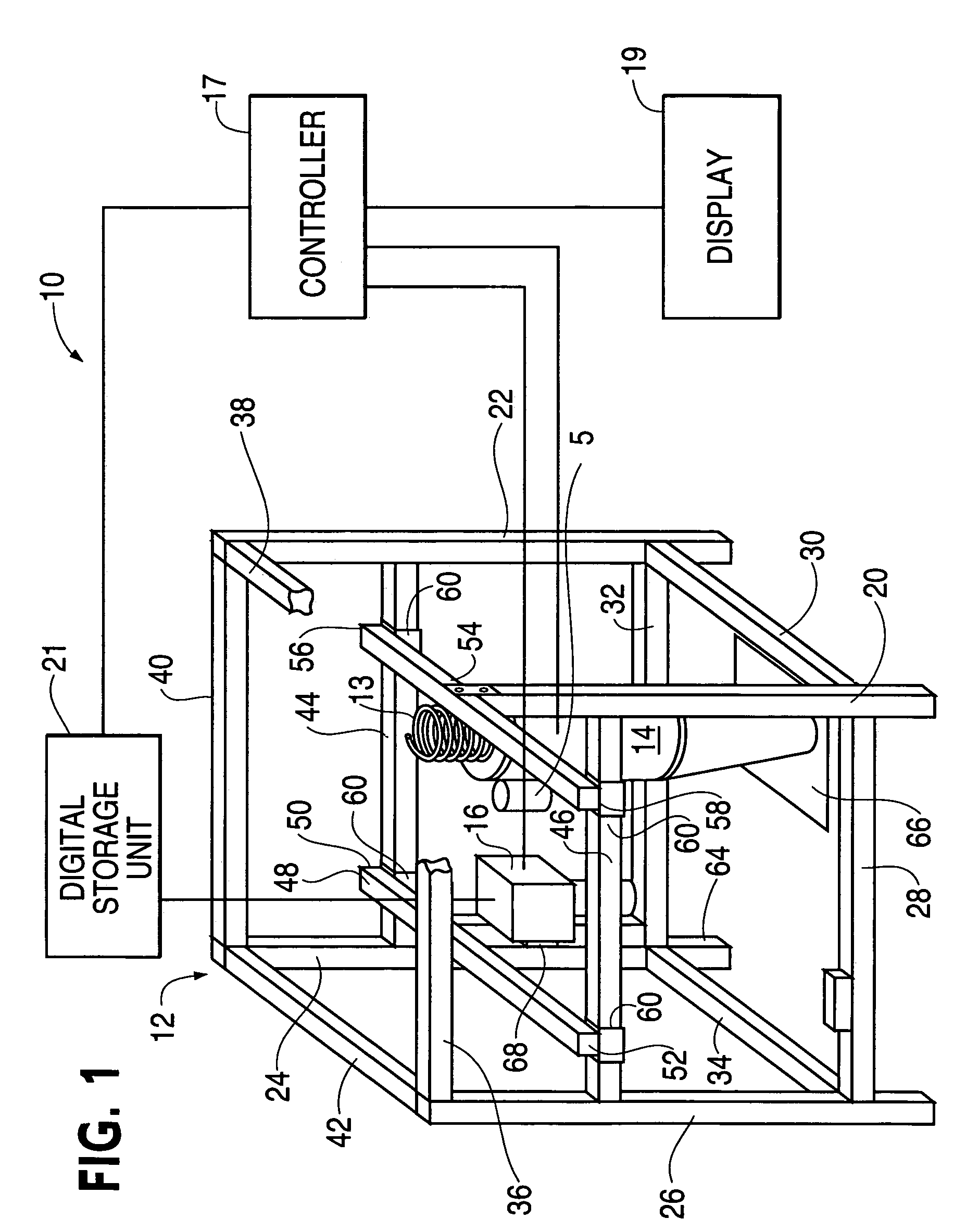
[0021]The present invention provides a translation frame to increase the speed for survey use of an ultrasonic thermography apparatus in the analysis and inspection of the structural integrity of metal and composite structures. The preferred embodiment is particularly suitable for use with airplanes and is suitable for inspecting subassemblies and in-service airplanes for defects such as disbonds, delaminations, cracks, corrosion, embedded contaminants, inclusions, and voids. It should be understood, however, that the present invention is not limited in its use with aerostructures, being usable, for example, for the inspection and analysis of pipelines, railroad rolling stock, architectural and civil engineering construction, and other structures where human safety or costly failure is a concern.

[0022]Detailed description of the operation of the mechanism within the frame referenced herein is contained in patent application Ser. No. 10 / 324,014, Ultrasonic Thermography Inspection Met...


PUM

PropertyMeasurementUnit
thermal imaging analysisaaaaaaaaaa
energyaaaaaaaaaa
thermal imaging cameraaaaaaaaaaa

Abstract

A portable thermal imaging apparatus uses an ultrasonic acoustical source and an infrared camera to examine a flat or curved specimen such as the surface of the fuselage of an aircraft for defects such as subsurface disbonds, delaminations, cracks, corrosion, embedded contaminants, inclusions, and voids. The apparatus includes a base framework removably attachable to the specimen by a set of vacuum cups and a pair of guide rails along which the imaging apparatus can travel to allow multiple images to be captured without relocating the apparatus on the specimen. The acoustical signal from the ultrasonic source sweeps over a range of frequencies in order to excite defects of greatly differing size to exhibit local heating.

Description

CLAIM FOR PRIORITY[0001]This application is a continuation-in-part of, and Applicants hereby claim the benefit of the filing date of, U.S. patent application Ser. No. 10 / 324,014, Ultrasonic Thermography Inspection Method and Apparatus, filed Dec. 20, 2002, the disclosure of which is incorporated herein in its entirety by reference.FIELD OF THE INVENTION[0002]The present invention relates to the use of ultrasonic thermography for inspecting the structural integrity of certain components, materials and / or structures. More particularly, the present invention relates to an apparatus and method for positioning an ultrasonic thermography test apparatus to ease and speed field inspections of aircraft fuselages and other structural components.BACKGROUND OF THE INVENTION[0003]Establishing and verifying the structural integrity of components and structures is important in many industries, such as aviation, automobiles, petroleum, and construction. Loss of structural integrity can be caused by...

Claims


Application Information

Patent Timeline
Patent Type & Authority Patents(United States)
IPC IPC(8): G01J5/02G01J5/48G01N25/72G01N29/04
CPCG01N25/72G01N2291/02827G01N2291/02881
Inventor THOMPSON, JEFFREY G.UYEHARA, CLYDE T.
Owner THE BOEING CO
Why Eureka
Try Eureka