
Scheme for label switched path loop detection at node device

a label switched path and node technology, applied in the field of node devices, can solve the problems of not being able to ascertain the node at which a loop is formed, the size of the label allocation message becomes quite large, and it takes a considerable amount of time to detect the loop, so as to achieve efficient and rapid detection of the label switched path loop

Inactive Publication Date: 2006-10-10
KK TOSHIBA
View PDF12 Cites 32 Cited by
  • Summary
  • Abstract
  • Description
  • Claims
  • Application Information

AI Technical Summary

Benefits of technology

The present invention provides a method for detecting label switched paths quickly and efficiently in a network. This is useful for constructing a label switched path in situations where a loop detection based on the TTL field of the IP packet is not applicable. The invention involves a node device that receives a label allocation message requesting a set up of a label switched path and exchanges it with a neighboring node on a route of one packet flow. The device then judges whether a label switched path loop is formed or not based on the input side label information and the ingress node information. The technical effect of this invention is to provide a more efficient and reliable method for detecting label switched paths in a network.

Problems solved by technology

However, for a packet to be transferred by the label switched path, the IP processing will not be carried out at an intermediate node so that it is impossible to decrement the TTL or the like, and consequently the packet will not leave the label switched path forever if there is a loop in the label switched path.
However, the above described method (1) has been associated with a problem that it takes a considerable amount of time until the loop detection because the presence of loop cannot be ascertained until the hop count exceeds the threshold.
Note that in this method if a loop is actually formed or not cannot be ascertained, and even if a loop is actually formed, it is impossible to ascertain a node at which a loop is formed.
On the other hand, the above described method (2) has been associated with a problem that the size of the label allocation message becomes quite large.

Method used


Image

  • Scheme for label switched path loop detection at node device
  • Scheme for label switched path loop detection at node device
  • Scheme for label switched path loop detection at node device

Examples


first embodiment

[0076]Referring now to FIG. 1 to FIG. 3, the label allocation protocol and the node device for carrying out the label switching according to this label allocation protocol according to the present invention will be described.

[0077]Here, it is assumed that the node device is separately carrying out an exclusive control by which the node device refuses to receive a message that requires a change of state from the previous hop node while waiting for an ACK signal after the message transmission to the next hop node.

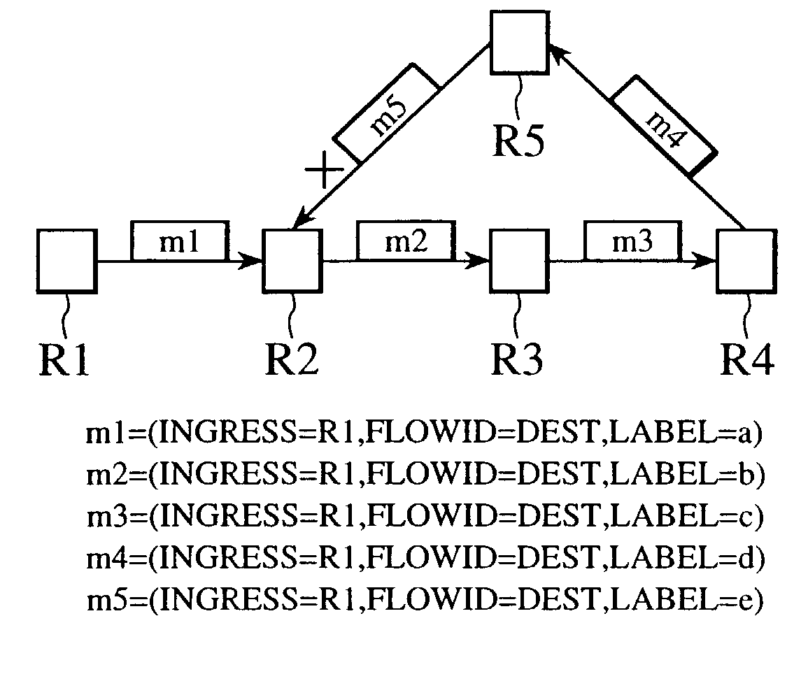
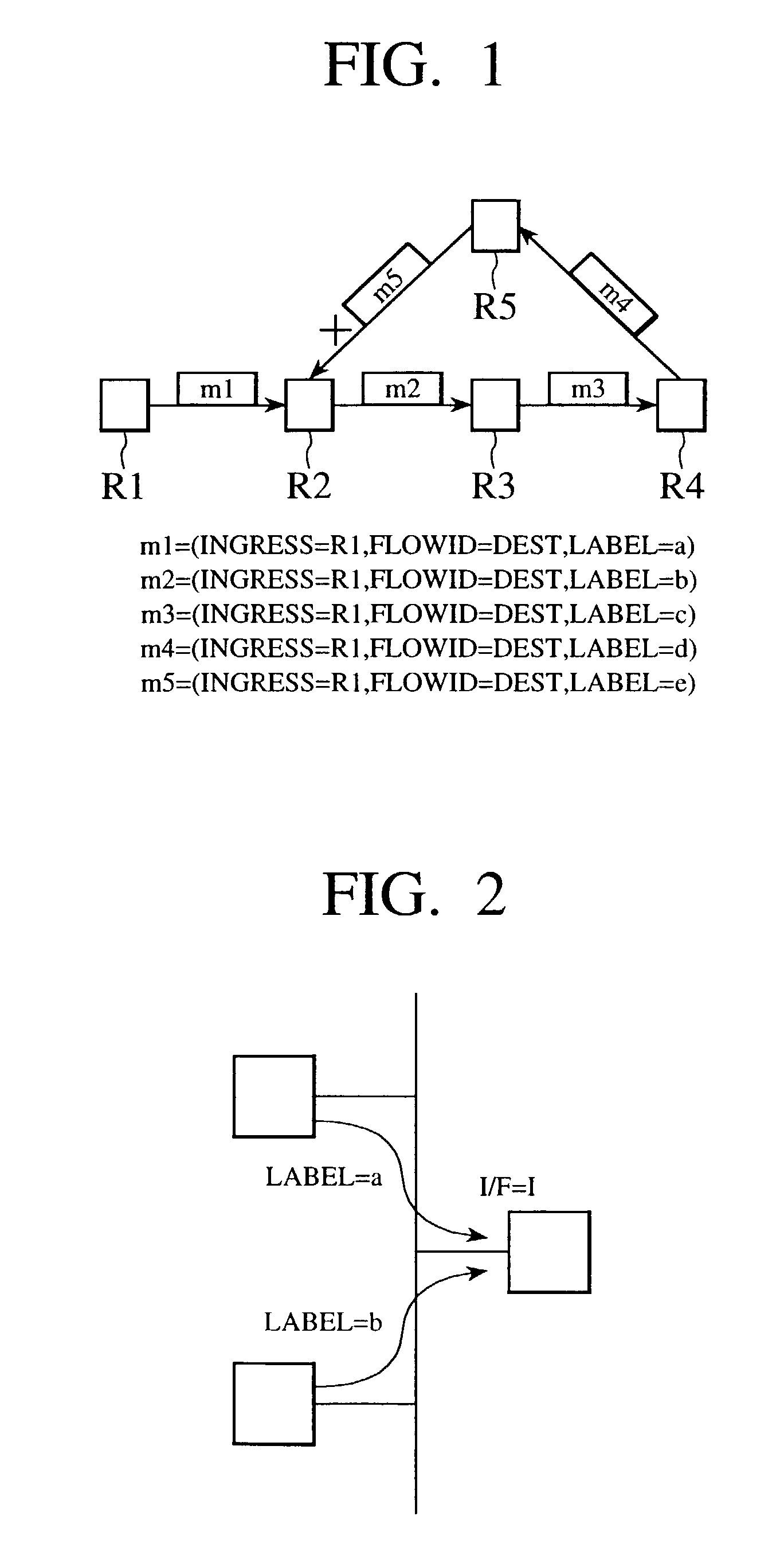
[0078]FIG. 1 shows an exemplary configuration of a network formed by connecting the node devices of this first embodiment together.

[0079]In FIG. 1, the node devices R1 to R5 of this first embodiment are connected together, and in particular, a loop is formed by the node devices R2 to R5. Note that FIG. 1 only shows a part of the entire network and a part of a whole of the node devices R1 to R5 are actually connected with other node devices (not shown).

[0080]Each of the node d...

second embodiment

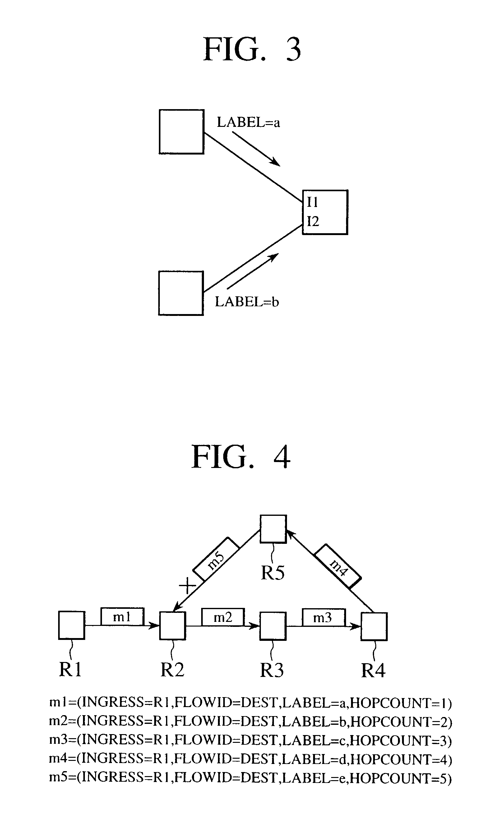
[0122]Referring now to FIG. 4 to FIG. 8, the label allocation protocol and the node device for carrying out the label switching according to this label allocation protocol according to the present invention will be described.

[0123]This second embodiment is basically similar to the first embodiment described above, so that the difference from the first embodiment will be mainly described in the following.

[0124]In this second embodiment, similarly as in the first embodiment, each node device has a function for carrying out the IP (Internet Protocol) processing, as well as a function for carrying out the label switching according to the label allocation protocol of this second embodiment (including the case of additionally using the hop count in the loop detection function of the first embodiment). In addition, except for those node devices which are located at network ends and do not carry out any relaying, each node device also has a router function. Also, it is assumed that the node...

fourth embodiment

[0338]In this fourth embodiment, the case of using the number of hops from the egress node as the hop count will be described, but the hop count may be omitted. The examples described below are all directed to the operation regarding a flow with a certain Flowid=Egress [R1] (a packet stream having R1 as an egress node).

[0339]Note that, in this fourth embodiment, the node address (R1 in the notation of Flowid=Egress [R1]) to be used for identifying the flow coincides with the node that actually becomes the egress of the label switched path, but in general, the node address to be used for identifying the flow may not necessarily coincide with the actual egress node of the label switched path. For example, in FIG. 25 which will be described in detail below, a node R0 (not shown) that is registered as an egress may exist as a next hop node of the node R1, in which case Flowid=Egress [R0] will be used, but the actual egress node of the label switched path is the node R1.

[0340]Now, some e...


PUM


Abstract

A node device and a label switched path loop detection method which are capable of detecting a label switched path loop efficiently and quickly are disclosed. In a node device for carrying out the label switching, an ingress node information is included in a message that is to be successively transmitted from the upstream side in order to set up a label switched path, and the fact that the message with the same ingress node information for the same packet flow will be received from a previous hop node that is different from before if the label switched path has a loop formed thereon is utilized. Also, at a time of transmitting a message for the purpose of setting up a label switched path, if a node at which the label switched path for that packet flow already exists on the upstream or downstream side is encountered, this already existing label switched path is traced along the same or opposite direction as the flow, and the label switched path is set up if no loop is detected after tracing to the end.

Description

BACKGROUND OF THE INVENTION[0001]1. Field of the Invention[0002]The present invention relates to a node device having a label switched path loop detection function and a label switched path loop detection method.[0003]2. Description of the Background Art[0004]In a network layer protocol in which IP (Internet Protocol) nodes are inter-connected on an NBMA (Non-Broadcast Multiple Access) network, there is a scheme for realizing high speed packet transfer called MPLS (Multi-Protocol Label Switching).[0005]In the MPLS, specific “labels” are allocated to specific packet flows between nodes while a correspondence between an input side label and an output side label is stored at each node, and the label switching is carried out at each node by referring to this information, so that the IP processing can be omitted and a high speed packet transfer can be realized. For example, in the case where the link layer is ATM, VPI(Virtual Path Identifier) / VCI (Virtual Channel Identifier) will be used...

Claims


Application Information

Patent Timeline
Patent Type & Authority Patents(United States)
IPC IPC(8): H04L12/28H04L12/50H04Q3/00H04L45/18H04L45/50H04Q11/04
CPCH04L49/309H04Q11/0478H04L2012/562H04L2012/5667
Inventor OHBA, YOSHIHIROTAKAHASHI, JUNICHIMATSUZAWA, SHIGEOKATSUBE, YASUHIRO
Owner KK TOSHIBA
Learn More