
Switch and a switching method

a technology of priority and switching method, which is applied in the field of priority enabled switching apparatus and method, can solve the problems of increasing overhead, reducing the efficiency of switching, and reducing the size of memory

Inactive Publication Date: 2008-06-12
WSOU INVESTMENTS LLC
View PDF9 Cites 26 Cited by
  • Summary
  • Abstract
  • Description
  • Claims
  • Application Information

AI Technical Summary

Benefits of technology

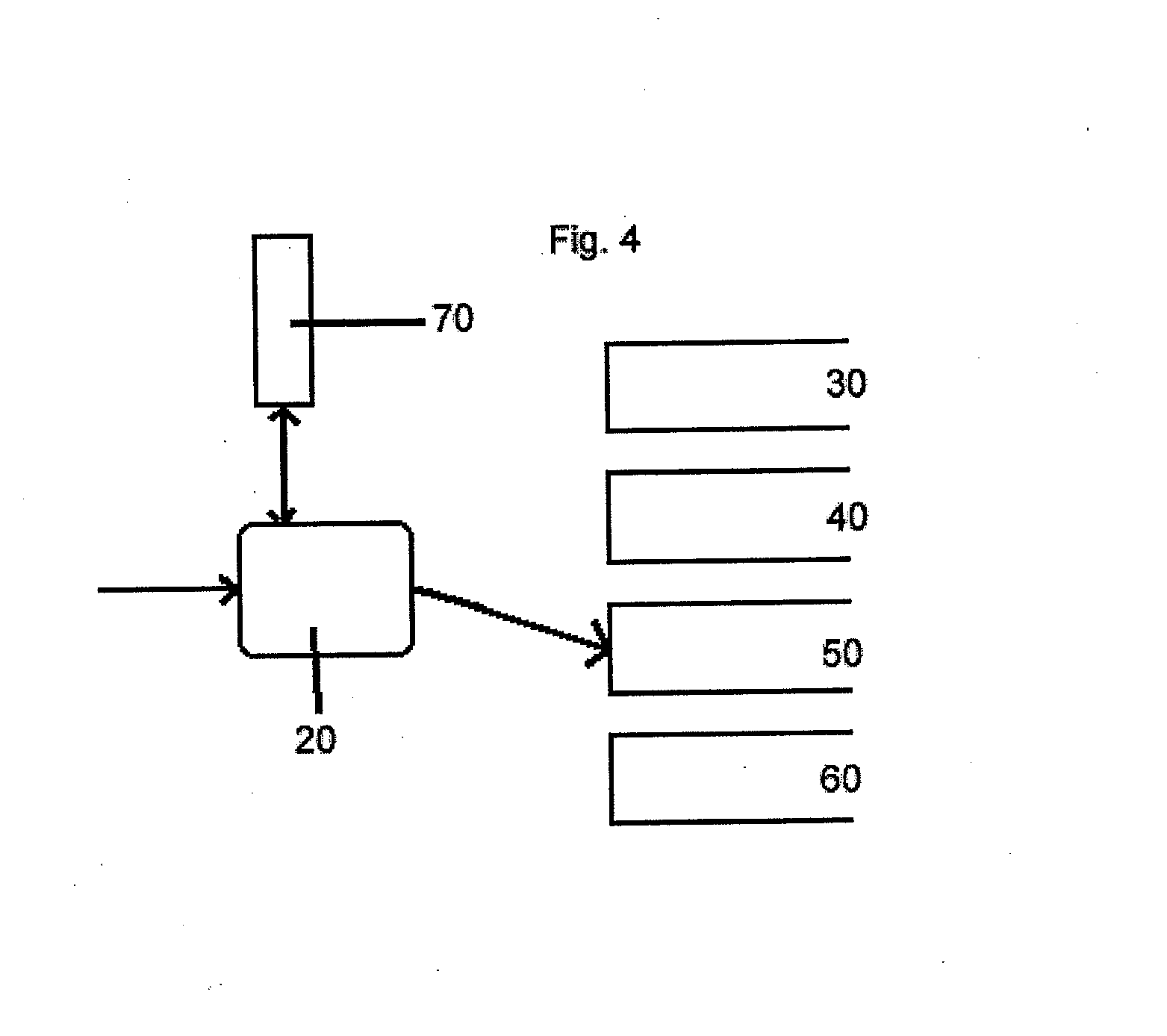
"The present invention provides a switch that can quickly and efficiently switch between different priority traffic streams without causing delays or interruptions. The switch includes queues for receiving traffic and a processor that controls the transmission of traffic from the queues. The processor is responsible for monitoring queues to determine if traffic has arrived from a higher priority queue and will interrupt the current transmission to prioritize the higher priority traffic. The processor can also adapt the traffic to include reassembly indicators for easy identification of individual packets or cells in the traffic. The invention offers a simple yet reliable and robust mechanism for reassembling interleaved packets or cells from a data stream. The switch can also include multiple outputs for transmitting traffic to different destinations. Overall, the invention provides a more efficient and effective solution for transmitting data traffic."

Problems solved by technology

In addition, the segmentation of information blocks for switching into smaller chunks, each with their own segmentation overhead, creates additional overhead.
(1) The queue memory size necessary to achieve a high load on transmission links, using large cells. This limitation can be relaxed however by advances in technology, which are making it possible to increase the size of memory at ever decreasing cost.
(2) The delay incurred by incoming high priority traffic while sending a low priority cell from a queue. This delay depends on the size of the low priority MSC, which cannot be too large in order not to disturb any higher priority MSC flow by too much. Alleviation of this limitation is harder to achieve since it would require an increase in memory speed and MSC processing speed.

Method used


Image

  • Switch and a switching method
  • Switch and a switching method
  • Switch and a switching method

Examples


Embodiment Construction

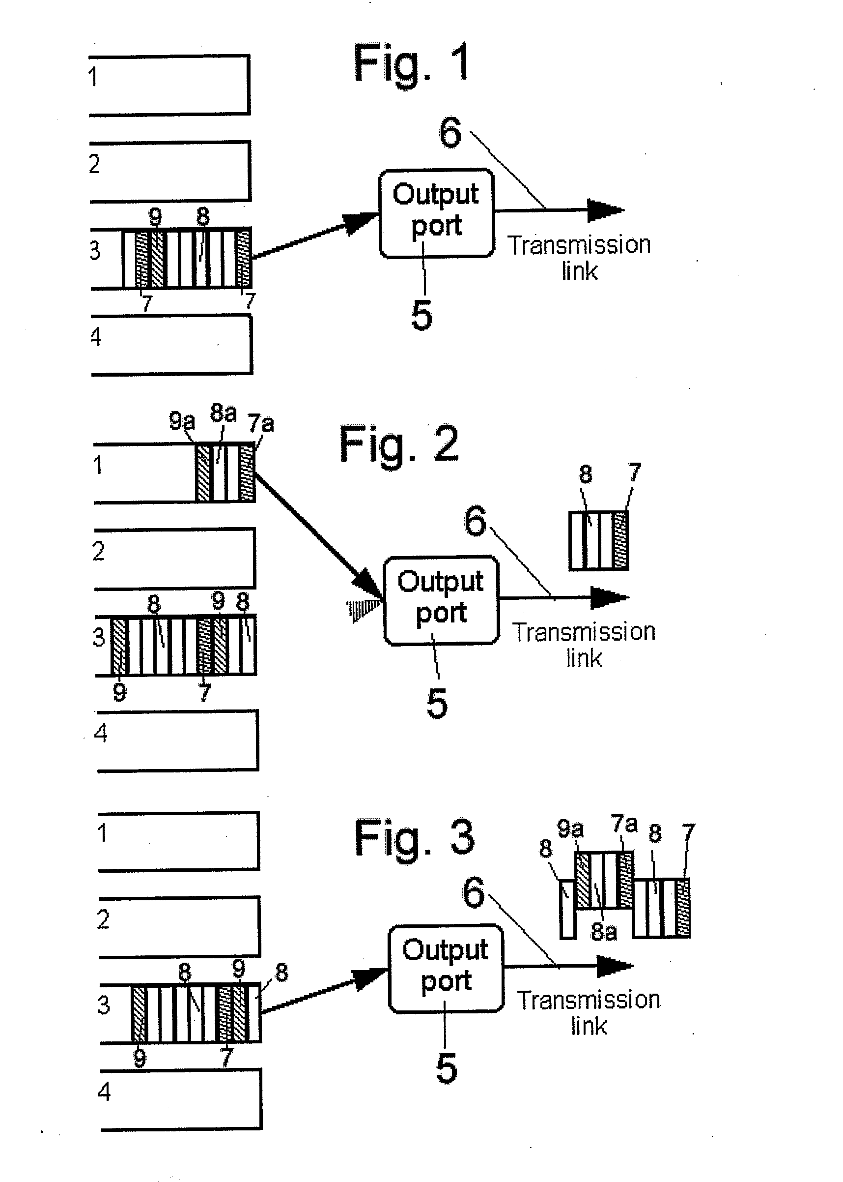
[0048]FIG. 1 is a representation of part of a switch including a number of input queues to be processed according to the present invention. Traffic, in the form of data elements such as slots, is received at queues 1-4. Queue 1 is predetermined to receive the highest priority switching treatment whilst queue 4 receives the lowest priority switching treatment. A processor (not shown) monitors traffic arriving at the queues to control the switching of traffic to an output port 5 which is connected to a transmission link 6.

[0049]A traffic stream received at queue 3 includes a start slot 7, a number of body slots 8 and an end slot 9. As there is no higher priority traffic waiting in other queues to be transmitted, the processor switches the traffic in queue 3 to the output port 5 starting with start slot 7, followed by body slots 8 and end slot 9.

[0050]However, if during transmission of the slots, traffic 7a-9a arrives at queue 1, it is detected by the processor. As the queue 1 is entit...


PUM


Abstract

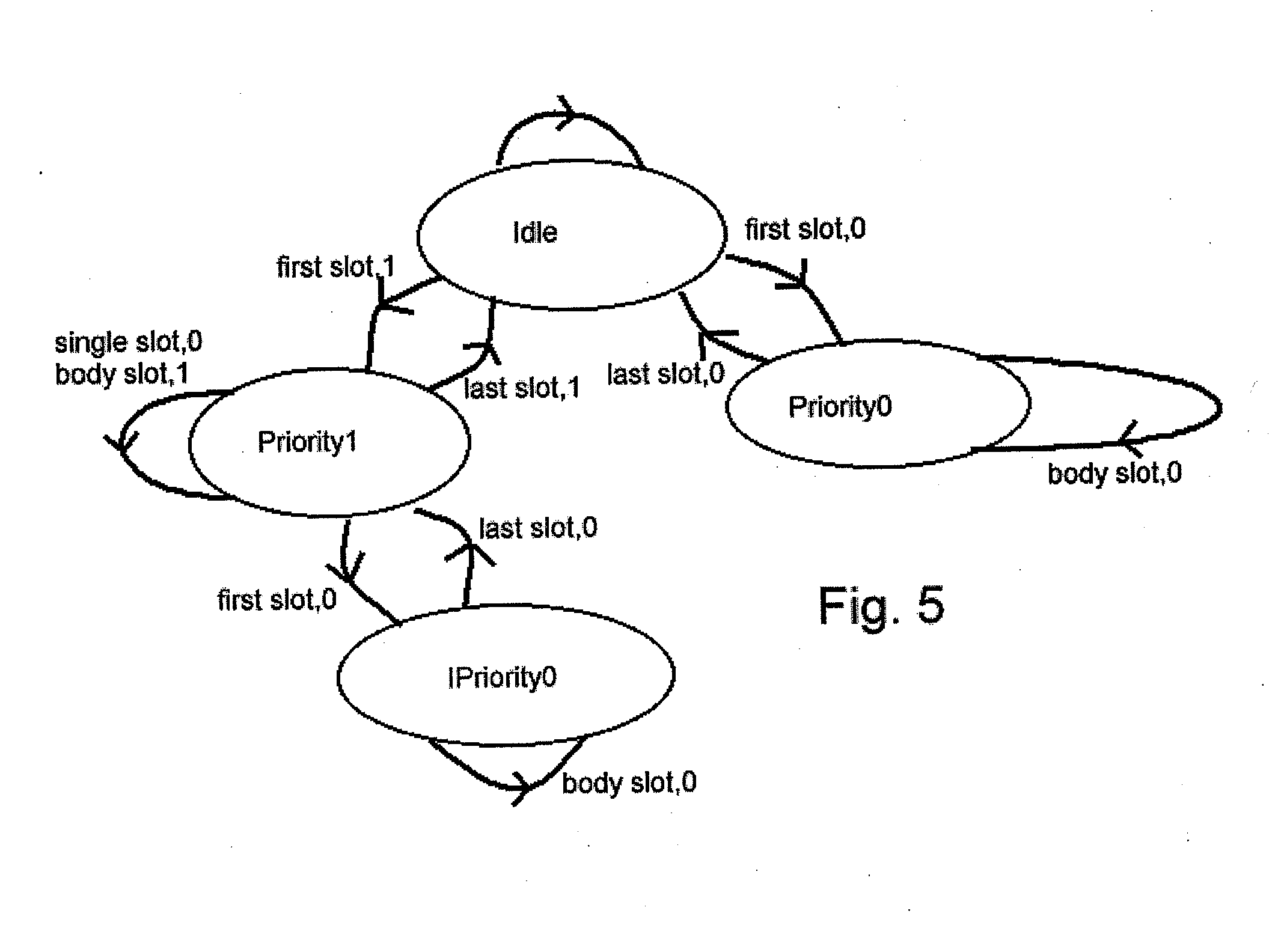
A switch at a transmission end of a system including a number of memory devices defining queues for receiving traffic to be switched, each queue having an associated predetermined priority classification, and a processor for controlling the transmission of traffic from the queues. The processor transmits traffic from the higher priority queues before traffic from lower priority queues. The processor monitors the queues to determine whether traffic has arrived at a queue having a higher priority classification than the queue from which traffic is currently being transmitted. The processor suspends the current transmission after transmission of the current minimum transmittable element if traffic has arrived at a higher priority queue, transmits traffic from the higher priority queue, and then resumes the suspended transmission. At a receiving end, a switch that includes a processor separates the interleaved traffic into output queues for reassembly of individual traffic streams from the data stream.

Description

[0001]This is a continuation of pending U.S. application Ser. No. 09 / 778,764 filed Feb. 8, 2001, which claims priority from European Patent Application No. EP 00400552.6 filed Feb. 28, 2000, the disclosures of each being hereby incorporated by reference in their entirety.BACKGROUND OF THE INVENTION[0002]The present invention relates to a priority-enabled switching apparatus and method for use in data communication networks and in particular, to a switching apparatus and method capable of multiple priority switching.[0003]In data communication networks, in particular local area networks (LANs) and wide area networks (WANs), the network infrastructure is built using equipment such as hubs and switches which link terminals to a network backbone and telecommunications links, thereby allowing the terminals to communicate with each other by some direct or indirect link, dependent on the network topology. Data is transmitted across networks as a series of packets. Packets are generated by ...

Claims


Application Information

Patent Timeline
Patent Type & Authority Applications(United States)
IPC IPC(8): H04L12/56H04L12/44H04L12/54H04L47/2416H04L47/56H04Q11/04
CPCH04L12/5693H04L47/2416H04L47/2425H04L47/2441H04L47/245H04L47/56H04Q11/0478H04L49/205H04L49/552H04L49/9094H04L2012/5651H04L2012/5681H04L47/6215H04L47/50
Inventor PAUWELS, BART JOSEPH GERARD
Owner WSOU INVESTMENTS LLC
Learn More