Optical fiber for long-distance optical communication network

a long-distance optical communication and optical fiber technology, applied in the field of optical fiber, can solve the problems of limited transmission distance, unsuitable for metro networks, and the tendency to experience a degraded transmission efficiency of 1550 nm

Inactive Publication Date: 2006-10-10
SAMSUNG ELECTRONICS CO LTD
View PDF14 Cites 20 Cited by
  • Summary
  • Abstract
  • Description
  • Claims
  • Application Information

AI Technical Summary

Benefits of technology

[0010]Accordingly, the present invention has been made to solve the above-mentioned problems occurring in the prior art and provides additional advantages, by providing an optical fiber used in long-distance optical communication networks for high-speed communication, such as metro networks and long-haul networks.

Problems solved by technology

However, the optical fibers having a dispersion value of −7 to −8 ps / nm / km at a wavelength of 1550 nm tend to experience a degraded transmission efficiency due to dispersion at a transmission rate of 2.5 Gbps.
Furthermore, they are not suitable for use in metro networks, which have a transmission distance of 100 km or more and a transmission rate of 10 Gbps, due to this excessively negative dispersion value.
However, this proposal has a problem in that, although the dispersion characteristics are suitable for metro networks for 200 km or less, it has a limited transmission distance due to a dispersion phenomenon in the case of long-haul networks for long-distance transmission of 200 km or more.

Method used


Image

  • Optical fiber for long-distance optical communication network
  • Optical fiber for long-distance optical communication network
  • Optical fiber for long-distance optical communication network

Examples


Embodiment Construction

[0022]Hereinafter, embodiments of the present invention will be described with reference to the accompanying drawings. For the purposes of clarity and simplicity, a detailed description of known functions and configurations incorporated herein will be omitted as it may make the subject matter of the present invention unclear.

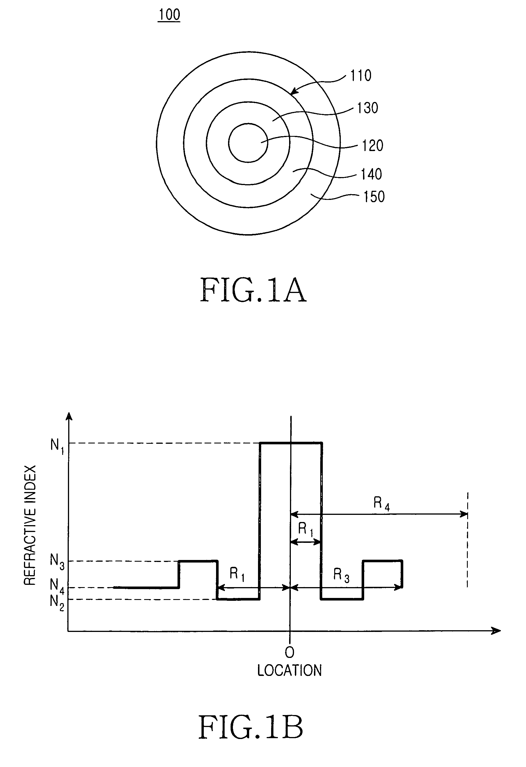
[0023]Referring to FIG 1a, an optical fiber 100 utilized in both metro networks and long-haul networks includes a core 110 and a clad 150. The core 110 is defined by a first region 120, a second region 130, and a third region 140.

[0024]The first region 120 has a radius R1 about the center of the optical fiber 100 and a refractive index N1, which is the maximum refractive index of the optical fiber 100.

[0025]The second region 130 surrounds the first region 120. The inner periphery of the depressed region 130 corresponds to the outer periphery of the first region 120. The outer periphery of the second region 130 has a radius R2 about the center of the optical fibe...


PUM


Abstract

An optical fiber for long-distance optical communication networks has a zero dispersion wavelength value in the range of 1560 to 1570 nm and a dispersion gradient value, at a wavelength band of 1550 nm, in the range of 0.055 to 0.075 ps / nm2 / km.

Description

CLAIM OF PRIORITY[0001]This application claims priority to an application entitled “optical fiber for long-distance optical communication network,” filed with the Korean Intellectual Property Office on May 13, 2004 and assigned Serial No. 2004-33748, the contents of which are hereby incorporated by reference.BACKGROUND OF THE INVENTION[0002]1. Field of the Invention[0003]The present invention relates to an optical fiber and, more particularly, to an optical fiber applicable in long-distance optical communication networks.[0004]2. Description of the Related Art[0005]In an effort to cope with an ever-increasing demand for higher capacity and speed, optical communication systems—namely, a WDM (wavelength division multiplex) technique that can perform a large-capacity transmission at high speed—are being deployed. The WDM systems may be classified into DWDM (dense wavelength division multiplex) systems and CWDM (coarse wavelength division multiplex) systems.[0006]The optical communicati...

Claims


Application Information

Patent Timeline
Patent Type & Authority Patents(United States)
IPC IPC(8): G02B6/02G02B6/036
CPCG02B6/02238G02B6/03644H04J14/02
Inventor OH, SUNG-KOOGHAN, JU-CHANGJANG, YUN-GEUN
Owner SAMSUNG ELECTRONICS CO LTD
Why Eureka
Try Eureka