Optical fiber for metro network

a technology of optical fiber and metro network, applied in the field of optical fiber, can solve the problems of ineffective nzdsfs in a network longer than 100 km, difficulty in providing good transmission characteristics of ssmfs, and many restrictive methods, and achieves high compatibility with existing metro networks, increased channel efficiency, and economic configuration.

Inactive Publication Date: 2006-10-03
SAMSUNG ELECTRONICS CO LTD
View PDF4 Cites 19 Cited by
  • Summary
  • Abstract
  • Description
  • Claims
  • Application Information

AI Technical Summary

Benefits of technology

[0017]One aspect of the present invention relates to an optical fiber with increased channel efficiency. For example, it may be economically configured and highly compatible for existing metro networks.

Problems solved by technology

However, such a method needs many restrictive requirements in order to achieve an effect on transmission characteristics.
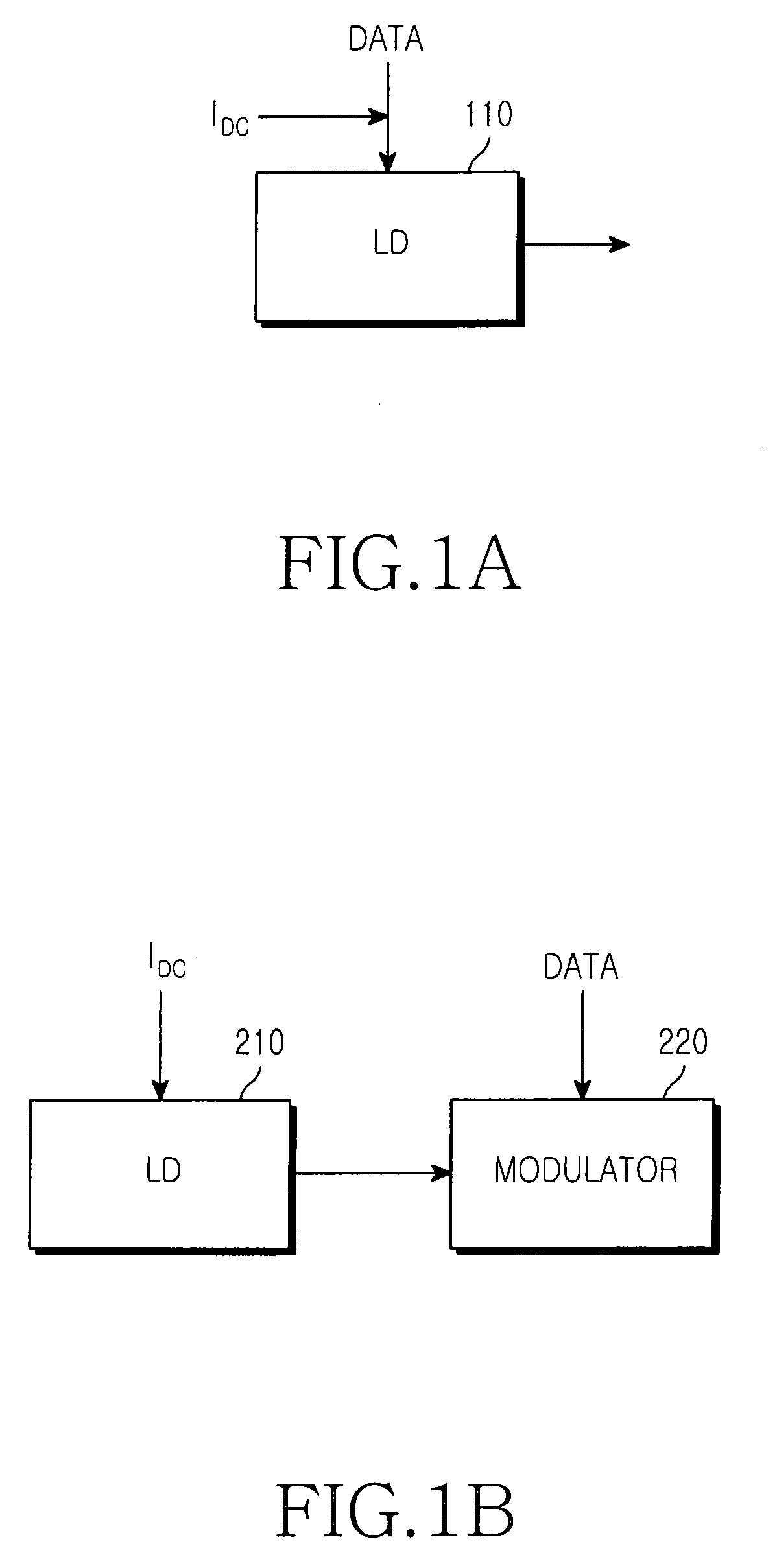
The SSMFs have difficulty providing good transmission characteristics due to the chirp phenomenon caused by the direct modulation, and the NZDSFs are not effective in a network longer than 100 km due to the excessively high negative dispersion values thereof.
When a metro network is configured using SMFs, configuring such a network become more complex because one or more separate dispersion control optical fibers must be used.
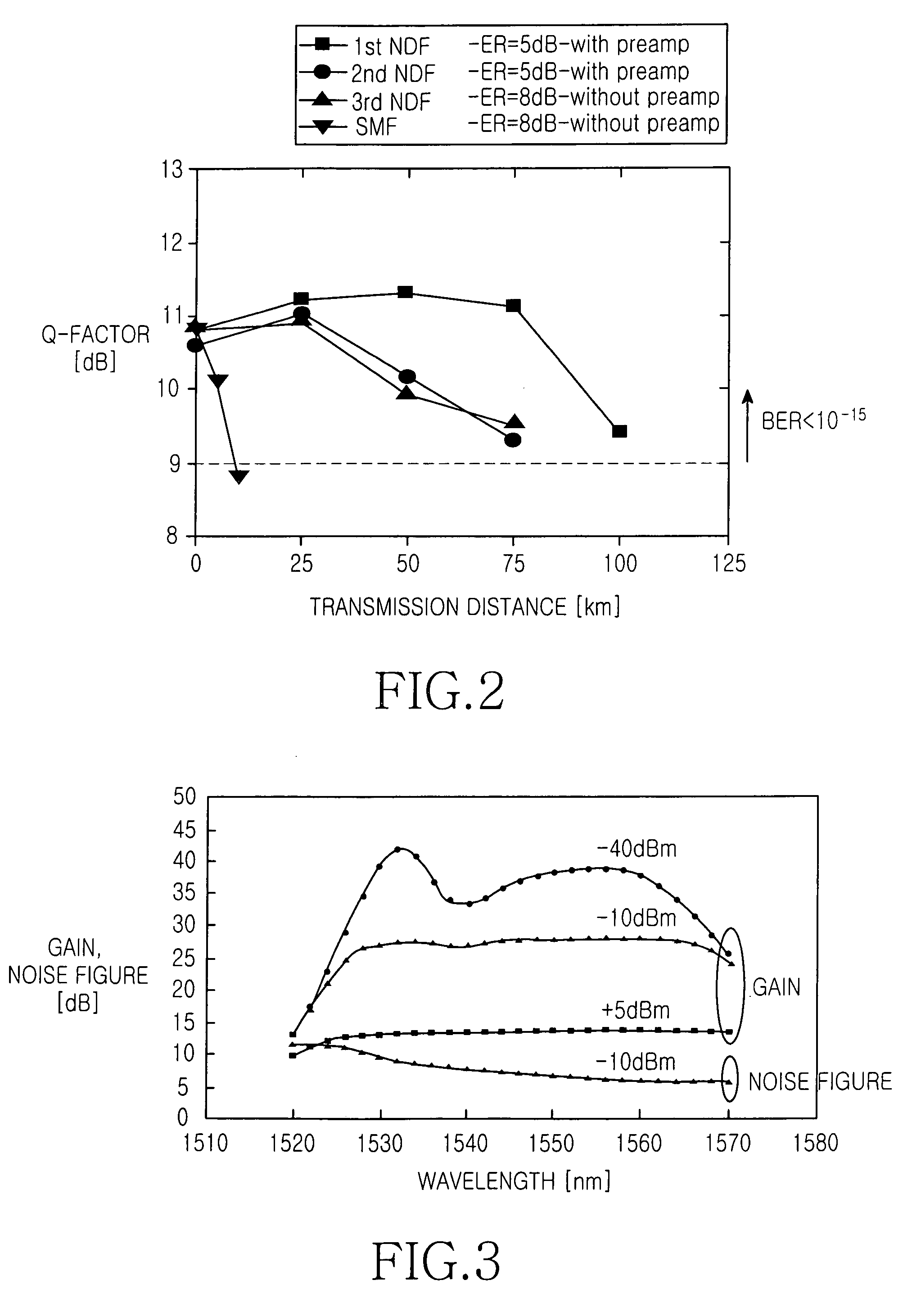
It can be seen that the typical SMF has difficulty providing good transmission characteristics due to the chirp phenomenon caused by the direct modulation, and the typical NDFs have a restriction in transmission distance in a metro network due to the high negative dispersion values thereof.
The NZDSF has a poor coupling efficiency with an existing optical fiber due to its complicated refractive index profile.
In addition, the NZDSF has a problem in that macro bending loss is very high due to its large refractive index depressed region.

Method used


Image

  • Optical fiber for metro network
  • Optical fiber for metro network
  • Optical fiber for metro network

Examples


Embodiment Construction

[0030]Hereinafter, embodiments of the present invention will be described with reference to the accompanying drawing. For the purposes of clarity and simplicity a detailed description of known functions and configurations incorporated herein will be omitted when it may obscure the subject matter of the present invention.

[0031]FIG. 5a shows the construction of an optical fiber for a metro network according to one embodiment of the present invention. FIG. 5b shows a refractive index profile of the optical fiber shown in FIG. 5a. The optical fiber 300 includes a core 310 having of a core region 320, a refractive index depressed region 330, and an annular region 340, and a clad 350.

[0032]The core region 320 has a radius R1 from the center of the optical fiber 300 and a refractive index N1. Here, N1 is the highest refractive index of the optical fiber 300 as compared to the refractive index depressed region 330, and the annular region 340 and the clad 350.

[0033]The refractive index depre...


PUM


Abstract

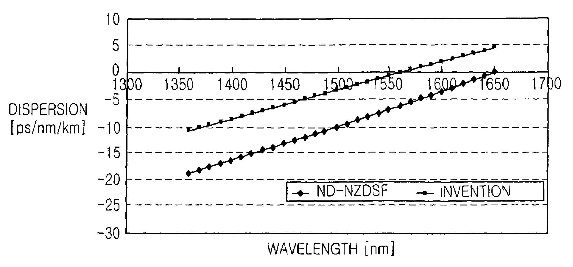
An optical fiber for an optical network is disclosed. The optical fiber includes a core having a core region having a first refractive index N1, and a refractive index depressed region surrounding the core region and having a second refractive index N2 that is lower than the first refractive index. A clad surrounds the core and having a third refractive index N4. The optical fiber has a zero-dispersion wavelength that is not less than 1555 nm and positioned in a wavelength range which does not exceed L-band. The optical fiber has negative dispersion values in C-band and positive dispersion values in L-band.

Description

CLAIM OF PRIORITY[0001]This application claims priority to an application entitled “Optical Fiber for Metro Network,” filed with the Korean Intellectual Property Office on Feb. 7, 2004 and assigned Serial No. 2004-8131, the contents of which are hereby incorporated by reference.BACKGROUND OF THE INVENTION[0002]1. Field of the Invention[0003]The present invention relates to an optical network, in particular to an optical fiber for use as a transmission line in such an optical metro-area network.[0004]2. Description of the Related Art[0005]In general, optical fibers, used in metro networks, have a negative dispersion characteristic. The fibers include core with a high refractive index and a clad surrounding the core. An annular region having a refractive index lower than that of the core may be interposed between the core and the clad.[0006]U.S. Pat. No. 4,715,679 to Bhagavatula, which is entitled “Low Dispersion, Low-Loss Single-Mode Optical Waveguide,” discloses a single mode optica...

Claims


Application Information

Patent Timeline
Patent Type & Authority Patents(United States)
IPC IPC(8): G02B6/02H04J14/02G02B6/00G02B6/036H01S3/10
CPCG02B6/02238G02B6/02276G02B6/03644H04B10/2525F23G5/0276F23G5/033F23L1/00F23L9/04F23G2201/303
Inventor JANG, YUN-GEUNOH, SUNG-KOOGHAN, JU-CHANG
Owner SAMSUNG ELECTRONICS CO LTD
Why Eureka
Try Eureka