Optical fiber and optical device

a technology of optical fiber and optical device, which is applied in the direction of optical waveguide light guide, optical light guide, instrument, etc., can solve the problems of increasing cost, difficult to set the zero dispersion wavelength to a wavelength shorter than 1200 nanometers, and difficult to achieve the effect of achieving the effect of achieving the effect of reducing the cos

Inactive Publication Date: 2010-02-23
FURUKAWA ELECTRIC CO LTD
View PDF13 Cites 18 Cited by
  • Summary
  • Abstract
  • Description
  • Claims
  • Application Information

AI Technical Summary

Problems solved by technology

Nevertheless, the wavelength where the zero dispersion wavelength can be easily set by adjusting the structure dispersion is equal to or longer than 1200 nanometers, and it is difficult to set the zero dispersion wavelength to a wavelength shorter than 1200 nanometers.
As a result, it is difficult to set the zero dispersion wavelength to a wavelength shorter than 1200 nanometers.
However, because it is difficult to fabricate the optical fiber in which such a larger number of holes are accurately arranged, the manufacturing yield becomes decreased resulting in an increase of cost.
Furthermore, in the photonic crystal fiber, a dopant for increasing the refractive index, such as germanium, is not doped in the core region, and the effective refractive index of the core region is low, which easily causes a large optical leakage loss.
Because a large number of hole layers are necessary to suppress the leakage loss, the total number of holes cannot be reduced, which causes a further decrease of the manufacturing yield and a further increase of cost.
However, regarding a single-mode optical fiber that has the zero dispersion wavelength at a wavelength near 1000 nanometers and is particularly suitable for a nonlinear optical device in this wavelength band, the photonic crystal fiber is not a good candidate because it is difficult to fabricate the fiber, which increases the cost.
Furthermore, in the case of the hole-assisted fiber, the shift of the zero dispersion wavelength to a wavelength near 1000 nanometers by controlling the structure dispersion increases the optical confinement, which leads the light to easily propagate in a higher-order mode, and therefore a single-mode operation at the zero dispersion wavelength becomes hard to obtain.

Method used


Image

  • Optical fiber and optical device
  • Optical fiber and optical device
  • Optical fiber and optical device

Examples


first embodiment

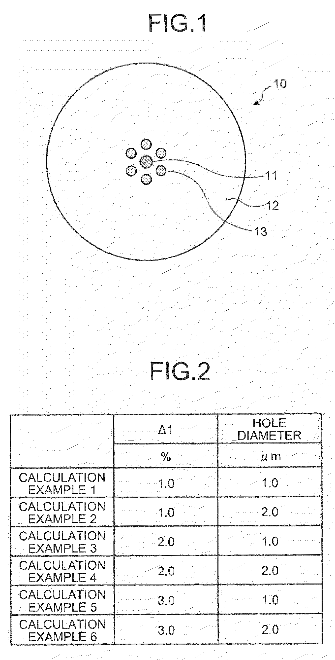
[0045]FIG. 1 is a schematic cross section of an optical fiber 10 according to the present invention. As shown in FIG. 1, the optical fiber 10 includes a core region 11 and a cladding region 12 formed on the outer circumference of the core region 11.

[0046]The core region 11 is made of germanium-doped silica glass. The cladding region 12 is made of pure silica glass that substantially does not contain a dopant for adjusting the refractive index and has a refractive index lower than a refractive index of the core region 11. A relative refractive index difference Δ1 of the core region 11 with respect to the cladding region 12 is, for example, 2.1%. The relative refractive index difference Δ1 is defined by Equation (1), where ncore is the maximum refractive index of the core region 11 and nclad is the refractive index of the cladding region 12.

Δ1={(ncore−nclad) / ncore}×100 (%)  (1)

[0047]The diameter of the core region 11 (core diameter) is, for example, 3.27 micrometers, and the diameter ...

third embodiment

[0096]As a modification example of the third embodiment, in the optical fiber 30, the core diameter of the core region 31 can be set to 3.8 micrometers, the relative refractive index difference Δ1 can be set to 1.3%, the hole diameter of each of the holes 33 can be set to 3.0 micrometers, and the distance L between the core region 31 and each of the holes 33 can be set to 0.65 micrometer. A calculation of the optical characteristics of the optical fiber according to the modification example by a simulation shows desirable characteristics that the zero dispersion wavelength is 1135 nanometers, the cutoff wavelength is 1000 nanometers, the effective core area is 10.6 μm2 at the wavelength of 1064 nanometers and 12.9 μm2 at the wavelength of 1550 nanometers.

[0097]As an embodiment example 3, the optical fiber according to the modification example is fabricated. The fabrication method for the optical fiber according to the embodiment example 3 is same as those for the optical fibers acco...

fourth embodiment

[0099]FIG. 25 is a schematic cross section of the optical fiber 40 and its refractive index profile. As shown in FIG. 25, the optical fiber 40 includes a core region 41 and a cladding region 42 formed on the outer circumference of the core region 41. The cladding region 42 has six holes 43 arranged around the core region 41. The holes 43 are arranged to make a six-fold rotational symmetry centering around the core region 41. In addition, in the optical fiber 40, the cladding region 42 further includes a low refractive index layer 42a formed around the core region 41.

[0100]In FIG. 25, a refractive index profile P1 shows a refractive index profile on a cross section that passes through the center axis of the core region 41 and that does not include the holes 43. In the figure, α11 shows the relative refractive index difference of the core region 41, and Δ21 shows the relative refractive index difference of the low refractive index layer 42a with respect to the cladding region 42 excl...


PUM


Abstract

An optical fiber includes a core region and a cladding region formed on an outer circumference of the core region. The cladding region includes a plurality of holes arranged around the core region and has a refractive index lower than a refractive index of the core region. A zero dispersion wavelength of the optical fiber is shorter than 1150 nanometers. The optical fiber propagates a light having a wavelength longer than 1000 nanometers exclusively in a fundamental mode of LP01 mode. An effective core area of the optical fiber is equal to or smaller than 12.0 μm2 at a wavelength of 1064 nanometers.

Description

CROSS-REFERENCE TO RELATED APPLICATIONS[0001]This application is a continuation of PCT international application Ser. No. PCT / JP2008 / 065770 filed Sep. 2, 2008 which designates the United States, incorporated herein by reference, and which claims the benefit of priority from Japanese Patent Application No. 2008-119078, filed Apr. 30, 2008, incorporated herein by reference.BACKGROUND OF THE INVENTION[0002]1. Field of the Invention[0003]The present invention relates to an optical fiber and an optical device employing the optical fiber.[0004]2. Description of the Related Art[0005]In recent years, a laser light source that outputs a high-power laser light having a wavelength near 1000 nanometers has been matured, which includes yttrium aluminum garget (YAG) laser having an oscillation wavelength of 1064 nanometers and an optical fiber laser using a ytterbium-doped optical fiber (YDF) having an oscillation wavelength of 1100 nanometers. With the development of such a laser light source, a...

Claims


Application Information

Patent Timeline
Patent Type & Authority Patents(United States)
IPC IPC(8): G02B6/032
CPCG02B6/02214G02B6/02366G02B6/03627G02F2001/3528G02F1/3528
Inventor MIYABE, RYOMUKASA, KAZUNORI
Owner FURUKAWA ELECTRIC CO LTD
Why Eureka
Try Eureka