

Wavelength division multiplexing optical transmission system
a transmission system and wavelength division technology, applied in the field of wavelength division multiplexing optical transmission system, can solve the problems of limited transmission distance and strong nois
- Summary
- Abstract
- Description
- Claims
- Application Information
AI Technical Summary
Benefits of technology
Problems solved by technology
Method used
Image

Examples
first embodiment
(First Embodiment)
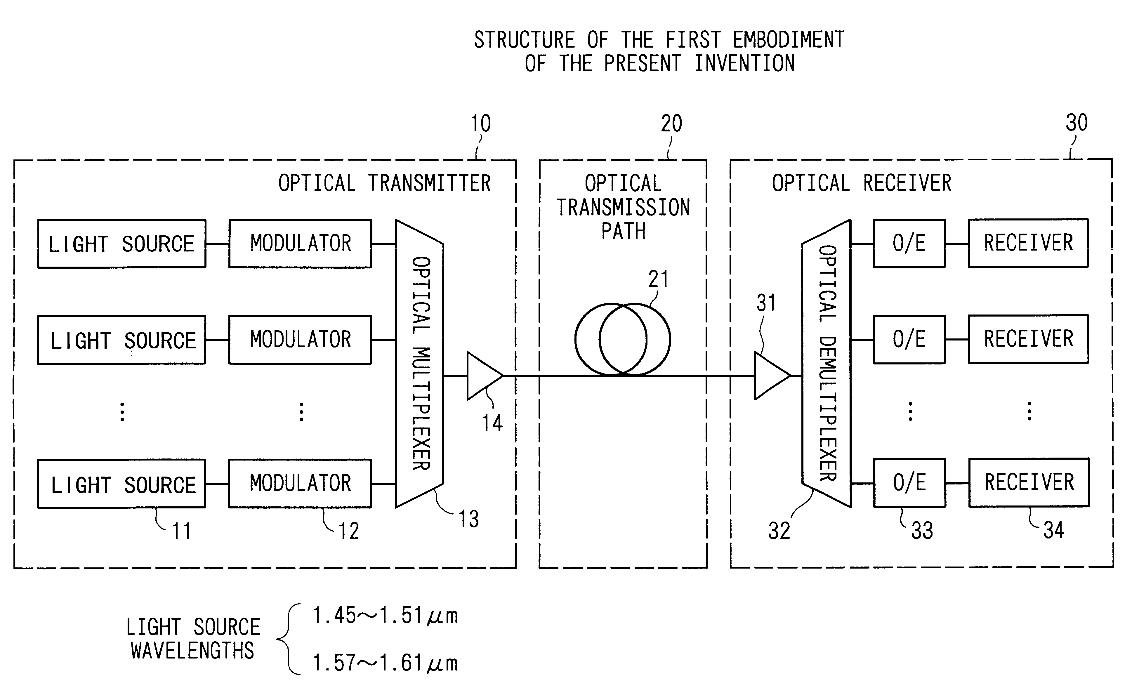
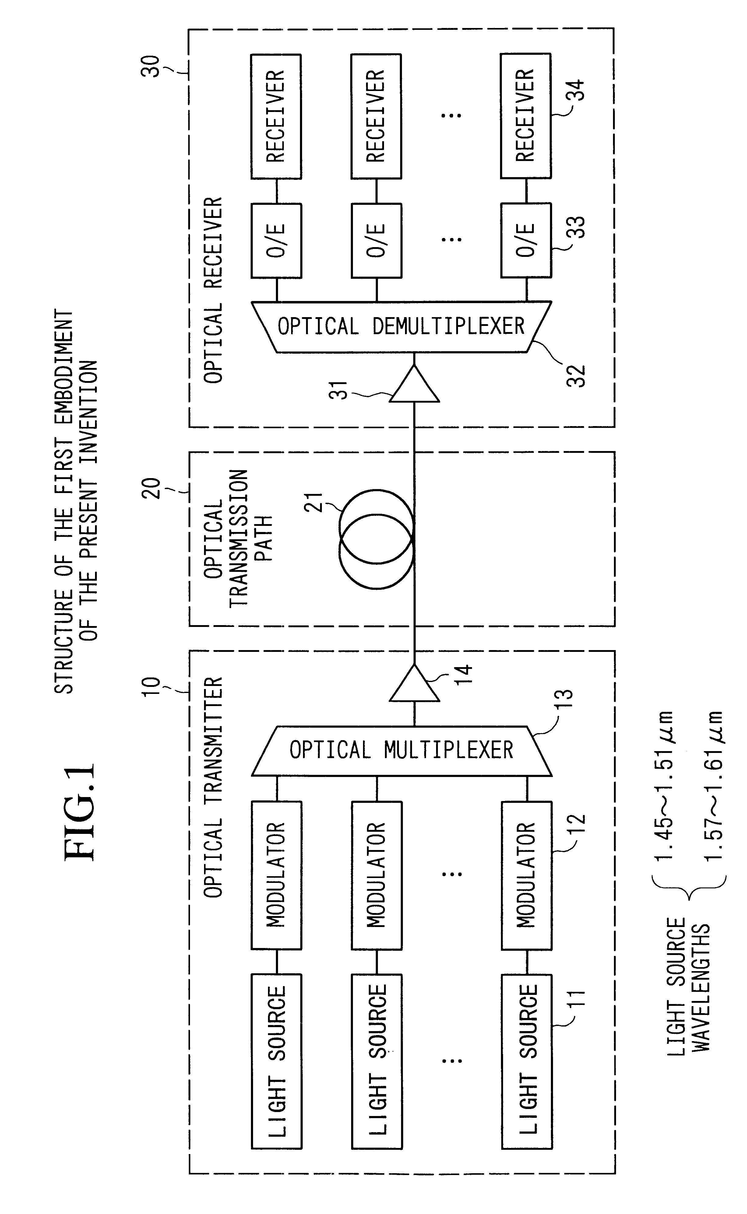
FIG. 1 shows the structure of the first embodiment of the present invention. The present embodiment shows an example of a nonrepeated point-to-point transmission system which connects opposite an optical transmitter and optical receiver without repeaters.
In the figure, the present system comprises an optical transmitter 10, an optical transmission path 20, and an optical receiver 30. Moreover, a system which directly modulates the bias, etc., of the light source can also be applied to the optical transmitter 10.
The optical transmitter 10 here uses an external modulating system, and comprises light sources 11 which set mutually differing wavelengths, modulators 12 which modulate the optical propagated wave output from the light source by a data signal, an optical multiplexer 13 which multiplexes optical signals output from each modulator 12, and an optical post-amplifier 14 which amplifies together the wavelength division multiplexed optical signal output from the o...
second embodiment
(Second Embodiment)
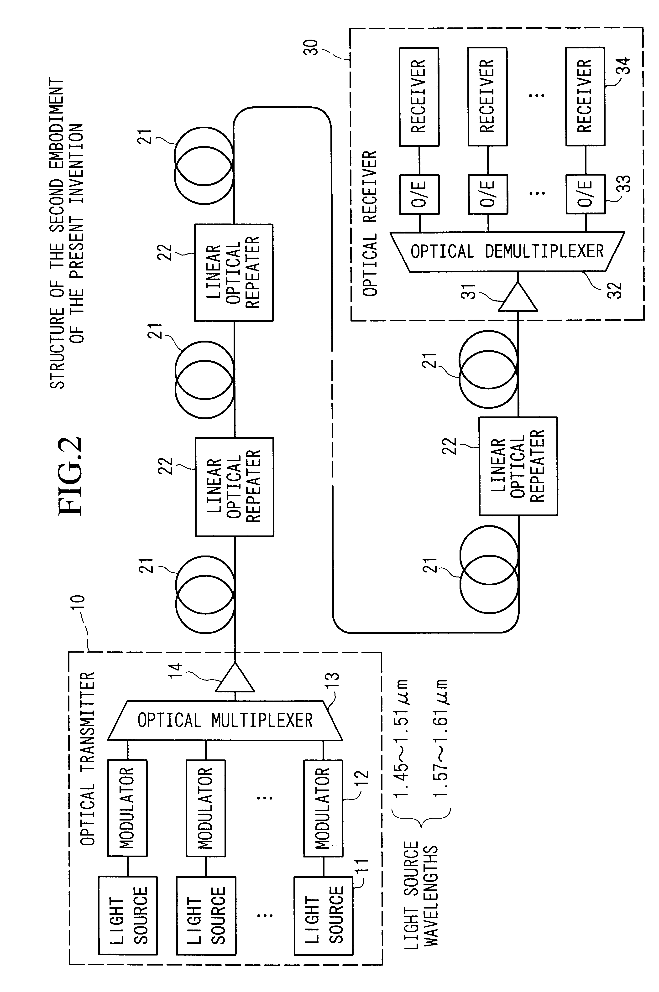
FIG. 2 shows the structure of a second embodiment of the present invention.
The characteristic of the present embodiment is found in disposing linear optical repeaters 22 along the optical transmission path which is a major structural component of an optical amplifier in order to compensate the propagation loss of the dispersion-shifted fiber 21 in the first embodiment. That is, this is an example of a multi-repeater point to point propagation system. In this manner, the propagation distance can be dramatically extended. The characteristics of the dispersion-shifted fiber 21 and the used wavelength band are the same as those of the first embodiment. The propagation distance like that in the present embodiment is long, and when the optical power is maintained at a high level by linear optical repeaters 22, in the conventional construction the degradation of the transmission quality due to four-wave mixing is severe, but in the structure which limits the used wavelen...
third embodiment
(Third Embodiment)
FIG. 5 shows the structure of the third embodiment. This embodiment is an example of the multi-repeater point-to-point transmission system which is similar to that of the second embodiment shown in FIG. 2. Those functions which are the same as those in FIG. 2 have the same reference numbers.
In the optical transmitter 10, the optical signal in the 1.45 .mu.m.about.1.51 .mu.m band is amplified by an optical post-amplifier 14A using a TDFA, such as the one shown in FIG. 3, and the optical signal in the 1.57 .mu.m.about.1.61 .mu.m band is amplified by an optical post-amplifier 14B using a GS-EDFA, such as the one shown in FIG. 4. In addition, the optical signals of both bandwidths are multiplexed by a bandwidth multiplexer WDM filter 41, and transmitted to the dispersion-shifted fiber 21.
In the linear optical repeater 22, the optical signals of both bands are demultiplexed by a bandwidth demultiplexer WDM filter 42, the optical signal in the 1.45 .mu.m.about.1.51 .mu.m...
PUM
 Abstract
Description
Claims
Application Information