Method for adjusting fan and compressor power for a vehicle cabin heating system

a technology for heating systems and compressors, which is applied in the direction of heat pumps, domestic cooling devices, lighting and heating devices, etc., can solve the problems of heat pump may consume more energy than is desired, and the vehicle in which the heat pump operates may provide less driving range than is desired, so as to reduce the output power of compressors, save energy, and achieve the effect of reducing the output power

Active Publication Date: 2015-06-11
FORD GLOBAL TECH LLC
View PDF19 Cites 10 Cited by
  • Summary
  • Abstract
  • Description
  • Claims
  • Application Information

AI Technical Summary

Benefits of technology

[0004]By weighing adjusting in evaporator fan power in response to compressor output power, it may be possible to provide the technical result of ascertaining whether or not it is beneficial to adjust evaporator fan input power to conserve energy used to operate a heat pump while providing a desired level of cabin heat. In particular, if increasing evaporator fan input power allows compressor output power to be reduced by an amount that is greater than the increase of evaporator fan input power speed while providing a desired level of cabin heat, the evaporator fan input power is increased. Otherwise, the evaporator fan input power may be maintained.
[0005]The present description may provide several advantages. Specifically, the approach may improve heat pump operating efficiency. Further still, the approach may extend vehicle driving range. Further still, the approach may provide a desired level of cabin heating while extending vehicle driving range.

Problems solved by technology

If the compressor and / or fan are driven at speed that are above or below desired speeds, the heat pump may consume more energy than is desired and it may provide more or less heat than is desired to the passenger cabin.
Consequently, the vehicle in which the heat pump operates may provide less driving range than is desired due to the fan and / or compressor consuming excess electrical energy from the vehicle.

Method used


Image

  • Method for adjusting fan and compressor power for a vehicle cabin heating system
  • Method for adjusting fan and compressor power for a vehicle cabin heating system
  • Method for adjusting fan and compressor power for a vehicle cabin heating system

Examples


Embodiment Construction

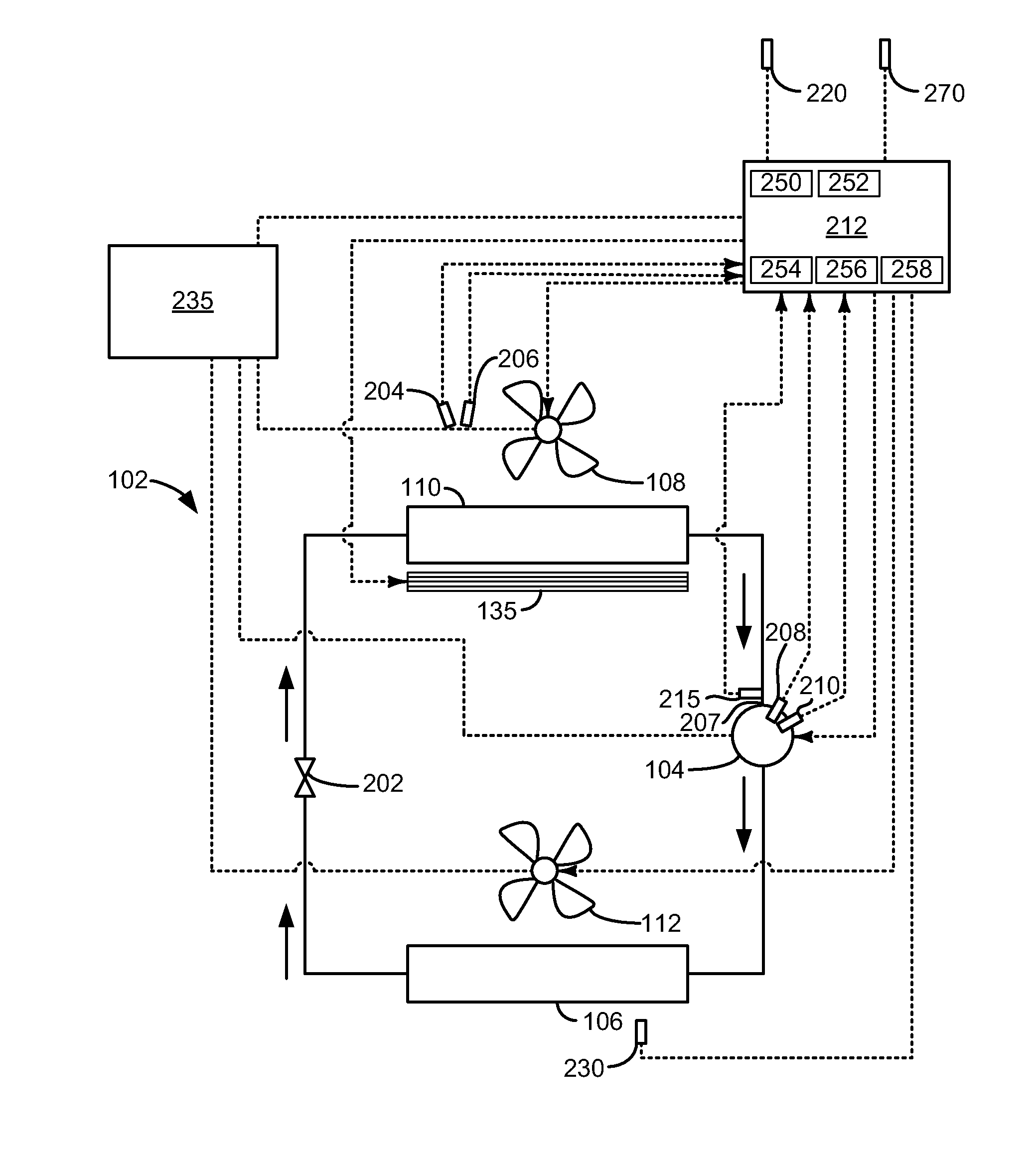
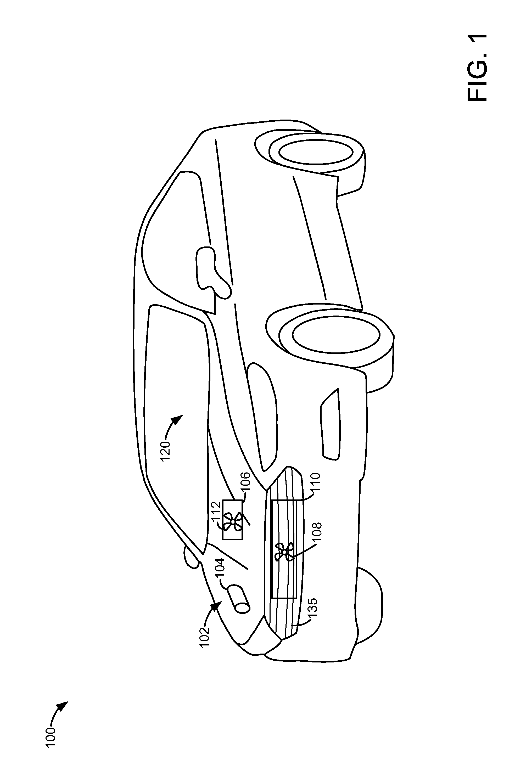
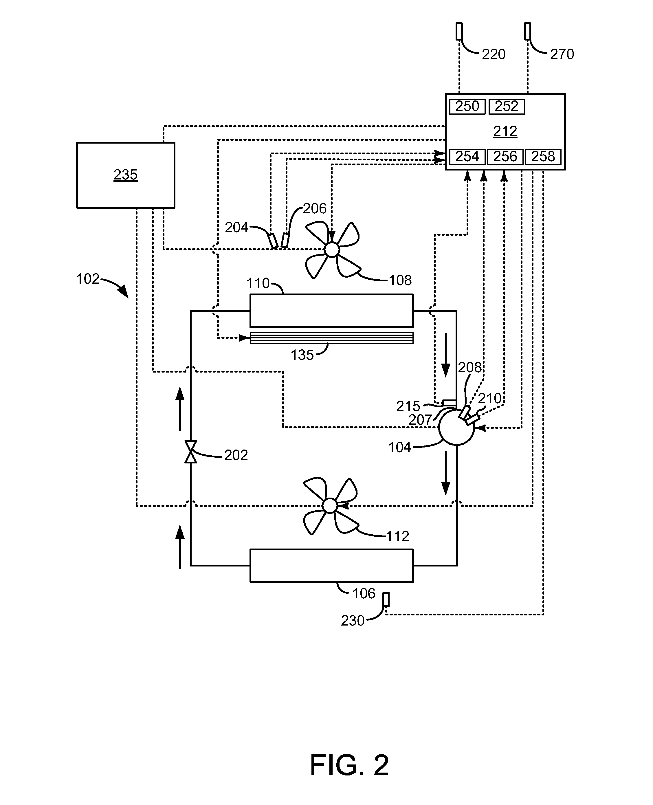
[0013]The present description is related to improving efficiency of a vehicle cabin heating system. The vehicle may be a passenger vehicle as shown in FIG. 1 or a commercial vehicle. The vehicle cabin heating system may include a heat pump as is shown in the heating system illustrated in FIG. 2. The vehicle cabin heating system may operate as shown in FIG. 3 according to the method of FIGS. 4 and 5.

[0014]Referring to FIG. 1, an example vehicle 100 that includes a heat pump 102 is shown. Heat pump 102 includes a compressor 104 that compresses a refrigerant for extracting heat from ambient air to heat passenger cabin 120. Heat pump 102 also includes an evaporator 110 and an evaporator fan 108. Evaporator fan 108 blows ambient air across evaporator 110 to extract heat from the ambient air. Heat pump 102 also includes condenser 106 and condenser fan 112. Ambient and / or cabin air is blown over condenser 106 by condenser fan 112 to cool refrigerant within heat pump 102 and heat passenger ...


PUM


Abstract

Systems and methods for operating a heater for a passenger cabin of a vehicle. In one example, fan speed of an evaporator cooling fan is adjusted to improve heating efficiency. In particular, fan speed is incrementally increased and maintained at the higher speed if output power of a compressor is reduced by more than an amount of power used to incrementally increase the fan speed.

Description

FIELD[0001]The present description relates to method for adjusting evaporator fan power and compressor power for a heat pump that provides heat to a cabin of a passenger vehicle. The method may be useful for electric and hybrid vehicles.BACKGROUND AND SUMMARY[0002]Vehicle passenger cabins may be heated using internal combustion engine waste heat that is transferred to engine coolant. Specifically, passenger cabin air and fresh air are blown across a heater core in which engine coolant circulates. Heat is transferred from the engine coolant to the cabin air and the cabin air is circulated about the cabin. However, some vehicles do not include an internal combustion engine, or the internal combustion engine may be stopped to conserve fuel so that little engine waste heat may be available to warm the passenger cabin. One way to heat cabin air within a passenger compartment of an electric or hybrid vehicle is to heat the cabin air via a heat pump. The heat pump extracts heat from ambien...

Claims


Application Information

Patent Timeline
Patent Type & Authority Applications(United States)
IPC IPC(8): B60H1/22F25B49/02F25D17/06
CPCB60H1/22F25B49/022F25D17/067B60H1/3213B60H2001/325B60H2001/3282F25B30/02F25B49/02F25B2700/15F25B2700/173F25B2700/1933F25B2700/2116
Inventor GREINER, CHRISTOPHER MARKWALLIS, MICHAEL STEVEN
Owner FORD GLOBAL TECH LLC
Why Eureka
Try Eureka