[0012] The optical fiber according to the present invention is preferably configured so that the mean zero dispersion
wavelength Be is in the range of 1440 nm to 1640 nm. This
wavelength band includes the S-band (1460 nm-1530 nm), C-band (1530 nm-1565 nm), and L-band (1565 nm-1625 nm), which are the bands generally used in optical communications, and it is easy to acquire an inexpensive high-output
laser source in the bands.
[0013] The optical fiber according to the present invention is preferably configured so that an effective area at the mean zero dispersion wavelength λ0 is not more than 15 μm2. In this case, the nonlinearity becomes so significant as to enable efficient
wavelength conversion.
[0017] The optical fiber according to the present invention is preferably configured so that a
crosstalk between orthogonal polarization components of fundamental mode light guided is not more than −15 dB at the overall length. In this case, where the optical fiber is a polarization-maintaining fiber, the influence of the
polarization mode dispersion can be substantially ignored, and it is feasible to exhibit the nonlinear
optical phenomena over a long period of time with extremely stability.
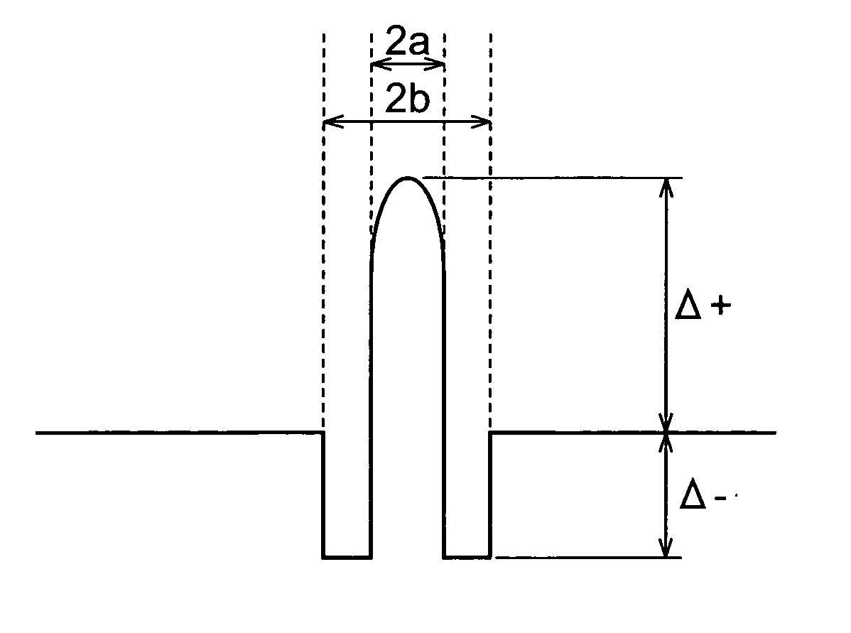
[0018] The optical fiber according to the present invention is preferably configured as follows: it further comprises at least a center core part having a maximum
refractive index N1 and an outside
diameter 2a, a depressed part surrounding the center core part and having a minimum
refractive index N2 and an outside
diameter 2b, and a cladding part surrounding the depressed part and having a maximum
refractive index N3; the refractive indices satisfy a relation of “N1>N3>N2”; with respect to the refractive index N3 of the cladding part, a
relative index difference of the center core part is defined as Δ+ and a
relative index difference of the depressed part as Δ−, and a difference “Δ+−Δ−” is not less than 2.2%; and a ratio Ra of the respective outside diameters of the center core part and the depressed part (=2a / 2b) is in the range of 0.2 to 0.7. When the optical fiber has the so-called W-
shape index profile and when the
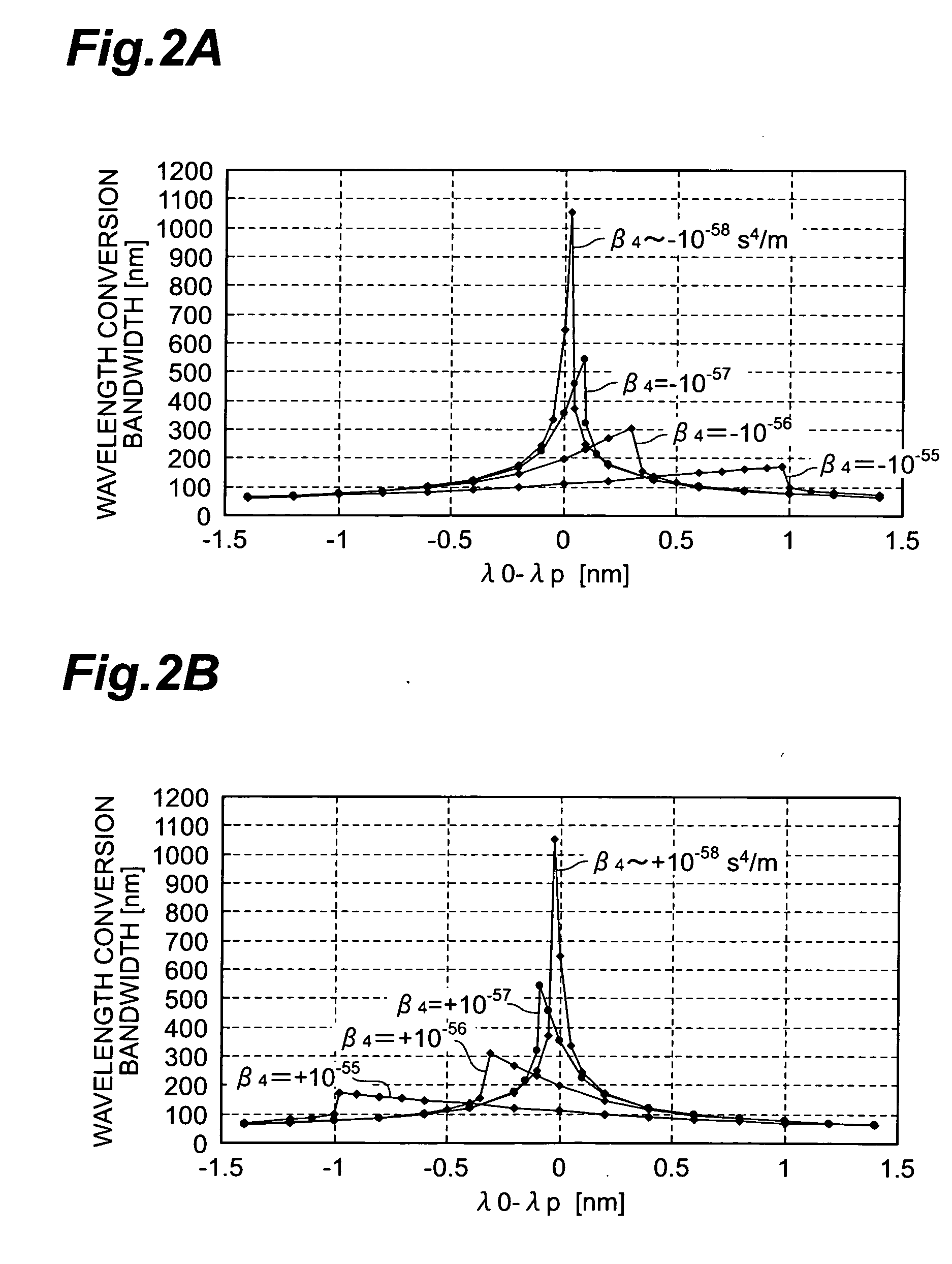
relative index difference Δ+ of the center core part, the relative index difference Δ− of the depressed part, and the ratio Ra satisfy the conditions as described above, it becomes easy to adjust the dispersion characteristics and to reduce the absolute value of the fourth order dispersion β4. The difference “Δ+−Δ−” is preferably not less than 3.1% and in this case, the
nonlinear coefficient can be increased to 20 / W-km or more. The relative index difference Δ− of the depressed part is preferably in the range of −0.1% to −1.1% and in this case, the absolute value of the fourth order dispersion β4 can be further reduced.
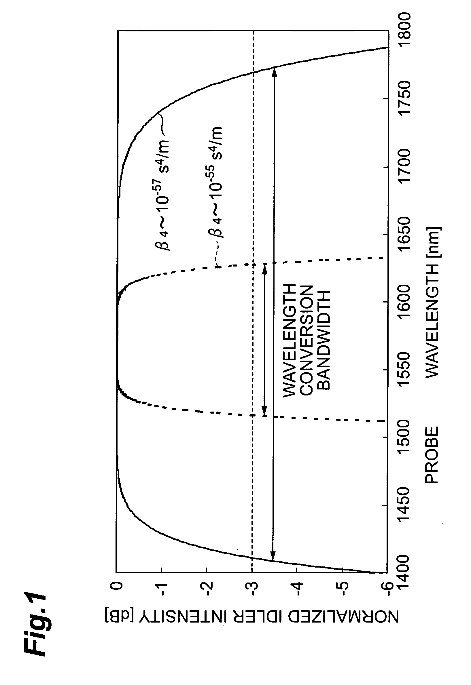
[0019] The optical fiber according to the present invention is preferably configured so that the fiber length is not more than 500 m. This facilitates expansion of the
wavelength conversion bandwidth.
[0021] An optical device according to the present invention is an optical device comprising: an optical fiber; a pump
light source for generating a pump light of a wavelength λP; and a probe
light source for generating a probe light of a wavelength λS, wherein the pump light and the probe light are guided through the optical fiber and an idler light of a new wavelength λI is generated from the optical fiber by a nonlinear optical phenomenon. The optical fiber in this optical device is preferably the optical fiber according to the present invention as described above. This optical device induces
wavelength conversion by four-wave mixing in the optical fiber to generate the idler light of the new wavelength λI different from both of the pump wavelength λP and the probe wavelength λS. Even if the wavelength spacing is wide between the pump wavelength λP and the probe wavelength λS, the wavelength conversion can be induced effectively. The pump light may be a pump of one wavelength, but may be a plurality of pumps of two or more wavelengths. The probe light may also be a probe of one wavelength, but may be a plurality of probes of two or more wavelengths. When control pulses are injected as the pump light into the optical fiber, the optical device can serve as an
optical switch making use of the wavelength conversion, or as an optical
demultiplexer. Since the optical device can generate a new
photon with the same information as a certain
photon of
signal light and of a wavelength different from that of the
photon, it can also generate a photon pair for
quantum encryption communication. Furthermore, the optical device is able to readily produce light of a wavelength at which there is no good
light source, and thus it can be applied not only in the
optical communication field but also in the other fields.

